0086-15068518279 (Chinese)/001-5416026691 (English)



 EN
EN
 中文简体
中文简体Content
A shaft leaves the centerless grinder at 12 microinches Ra just before lunch. By mid-afternoon the same setup is producing 24 microinches Ra. The print has not changed, the wheel looks freshly dressed, and the coolant system is running normally. Yet the surface finish has drifted by 100 percent. Most shops run into this pattern sooner or later, and the fix is rarely a single dial or a new wheel. Centerless grinding surface finish is the result of three interacting groups of variables — wheel condition, machine support geometry, and process parameters — and it becomes predictable only when all three are controlled together.
Centerless grinding is one of the most productive finishing processes for cylindrical parts. Because the workpiece rides on a work rest blade between a grinding wheel and a regulating wheel, there is no need for center holes, chucks, or tailstocks. That makes the process a natural fit for bars, pins, rollers, valve spools, and other round components that have to hold tight tolerances at high volumes. It is also why the surface finish it produces is so often the deciding factor in the industries where centerless grinding is most widely used.
What surface finish can centerless grinding actually hold?
Start with realistic numbers before changing any setup. In production, centerless grinding typically achieves surface finishes from 32 down to 4 microinches Ra, which is roughly 0.8 to 0.1 µm Ra. The value a given job can reach depends on the process mode, the wheel specification, and how much stock has to be removed.
| Process mode | Typical Ra range | Best suited for |
|---|---|---|
| Through-feed (production) | 16–32 µin Ra (0.4–0.8 µm) | High-volume bars, pins, rollers |
| In-feed (plunge) | 8–16 µin Ra (0.2–0.4 µm) | Shouldered and stepped parts |
| Fine-finish setup | 4–8 µin Ra (0.1–0.2 µm) | Precision shafts, valve components |
The ranges above assume a machine in good condition, a freshly dressed wheel, and stable thermal conditions. If you want to know how accurate centerless grinding can be, the short answer is that roundness and straightness of 0.0002 in or better are realistic while the surface finish is being generated in the same pass. The process is not only fast; it is accurate. The finish side, however, is more sensitive to setup than the geometry side, which is why the same machine can produce very different Ra values on different days.
Machine-side variables that set the finish ceiling
Before touching feeds and speeds, check the three machine-side factors that decide what finish the process is physically capable of producing.
Grinding wheel specification and dressing
Grit size is the most obvious variable. A 46-grit wheel removes stock quickly but leaves a coarse scratch pattern, while an 80-grit or 120-grit wheel generates a visibly finer finish. Bond and grade matter just as much. A hard bond holds the wheel profile longer but can glaze and burn the workpiece; a softer bond releases dull grains and cuts cooler, which is why finish wheels are often one grade softer than roughing wheels.
Dressing is where most finish problems actually begin. The dressing feed rate controls how much grain protrudes from the wheel face. A fast dress at 0.05 mm/rev or more opens the wheel for aggressive cutting but leaves a rough cutting surface. For a fine finish, dress slowly, around 0.02 to 0.03 mm/rev, and take a light pass with a sharp diamond before the first finishing cycle.
Regulating wheel and speed ratio
The regulating wheel controls both workpiece rotation and through-feed rate. The speed ratio between the grinding wheel and the workpiece determines how many cutting grains pass over the surface per second. Higher grinding-wheel-to-workpiece speed ratios produce finer finishes because each grain takes an increasingly thin chip. Slowing the regulating wheel, or reducing its tilt angle to lower the through-feed rate, is often the fastest way to improve Ra on a machine that is already running.
Blade height and work rest support
The work rest blade carries the workpiece, and its height relative to the wheel centerline controls the geometry of the contact zone. If the blade is set too high, the part vibrates and chatters; if it is too low, the part can develop lobing. Most operators position the blade using the recommended centerline offset for the workpiece diameter and then fine-tune it until any chatter disappears. Blade wear and a dirty blade surface transfer directly into scratches and uneven finish.
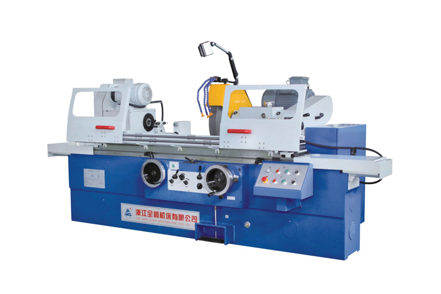
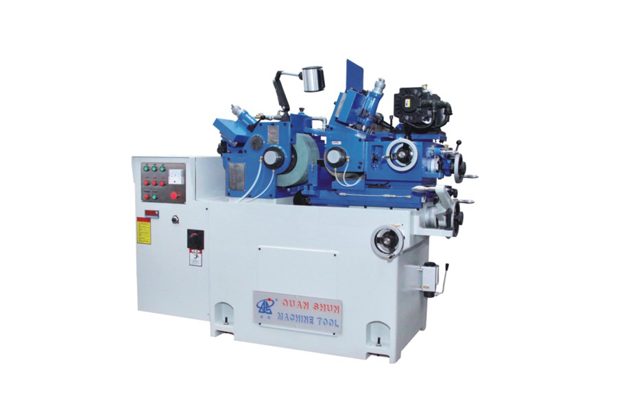
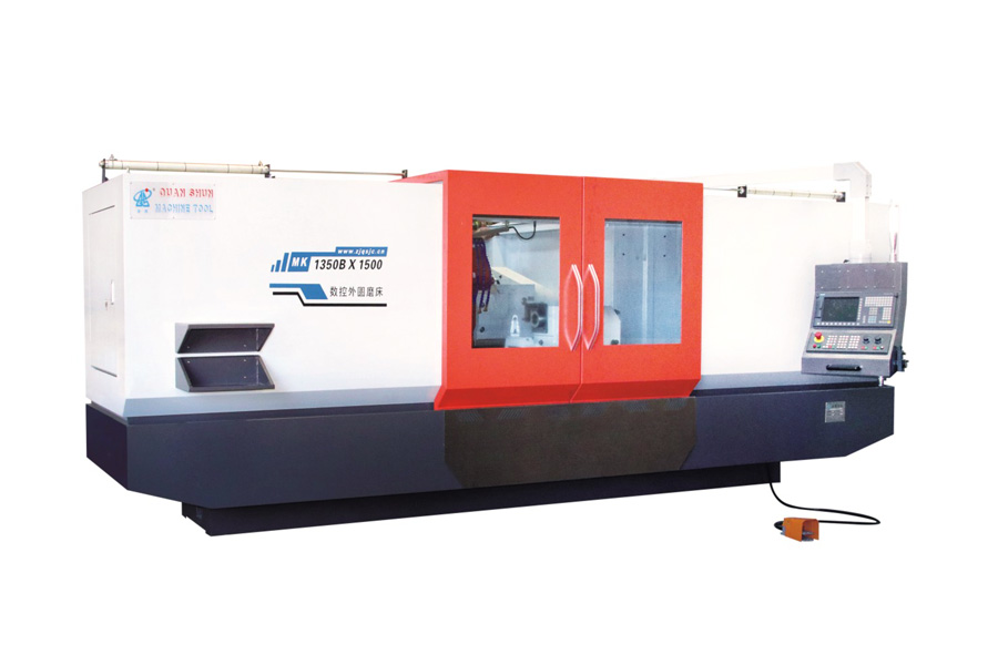
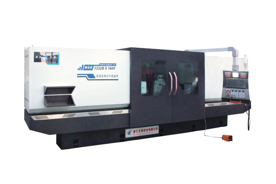
These machine-side variables only work as well as the machine carrying them. Static rigidity and spindle accuracy decide how far a setup can be pushed. A machine with a heavy cast bed, well-damped guideways, and balanced wheels will hold its settings across a long production run. For shops that need continuous high-volume output with a predictable finish, the centerless grinding machines we manufacture are built around exactly these stability requirements, with a rigid structure and precisely aligned spindles that keep vibration out of the cut.
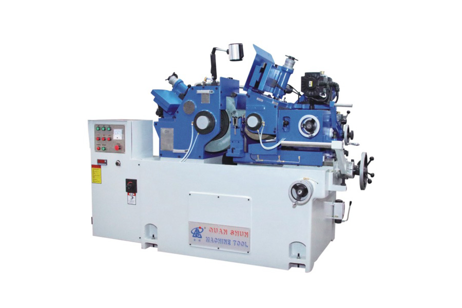 Wholesale Centerless Grinding Machine Manufactures, FactoryAs a China Centerless Grinding Machine manufacturer and Centerless Grinding Machine factory, Zhejiang Quanshun Machine Tool Co., Ltd spec...View Product →
Process parameters that turn capability into repeatable Ra
Once the machine-side setup is correct, the process parameters determine whether the finish repeats part after part and shift after shift.
Spark-out time and pass strategy
Spark-out is the time or number of rotations after the wheel stops advancing. During spark-out the wheel continues to remove chips of decreasing thickness, which relaxes the elastic deflection in the machine and workpiece. Two to five seconds of spark-out can improve the Ra value by a full finishing class in in-feed grinding. In through-feed grinding, a lighter depth of cut on the final pass has a similar effect.
Coolant filtration and delivery
Coolant does more than prevent burn. It flushes swarf out of the contact zone and keeps the wheel face open. Contaminated coolant is one of the leading causes of random scratches and inconsistent finish in centerless grinding. Filter the coolant to at least 20 µm, direct the nozzle so the stream hits the grinding zone squarely, and keep the flow rate and temperature stable. A drift in coolant temperature changes the machine's thermal state, and the finish follows it.
Roughing and finishing feed strategy
When a part needs both stock removal and a fine finish, do not try to do both in a single pass. Use a coarser wheel and a heavier feed to remove the bulk of the material, then reduce the feed for a finishing pass of about 0.005 to 0.01 mm. For parts that must remain below 8 Ra, multiple passes with decreasing infeed are more reliable than one aggressive pass followed by extended spark-out.
Match the machine to the finish requirement
Centerless grinding is the right choice for round parts without centers, especially long bars and small-diameter components. But the process has limits. Parts with shoulders, keyways, splines, or other interrupted surfaces are difficult to support on a work rest blade, and the finish often degrades at the interruption. Parts that must keep their center holes, or parts with an unusually high length-to-diameter ratio, are also better finished on a cylindrical grinder, where the workpiece is held between centers and the diameter, face, and multiple steps can be ground in one clamping.
- Shouldered and multi-diameter shafts that cannot pass through the regulating wheel
- Parts with center holes that must stay accurate for later operations
- Interrupted surfaces such as keyways and splines that create vibration on a blade
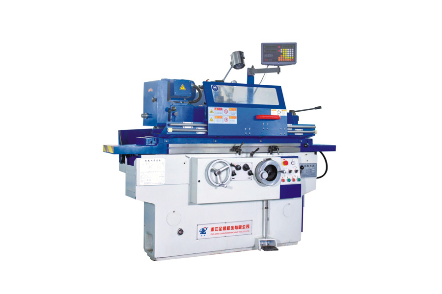
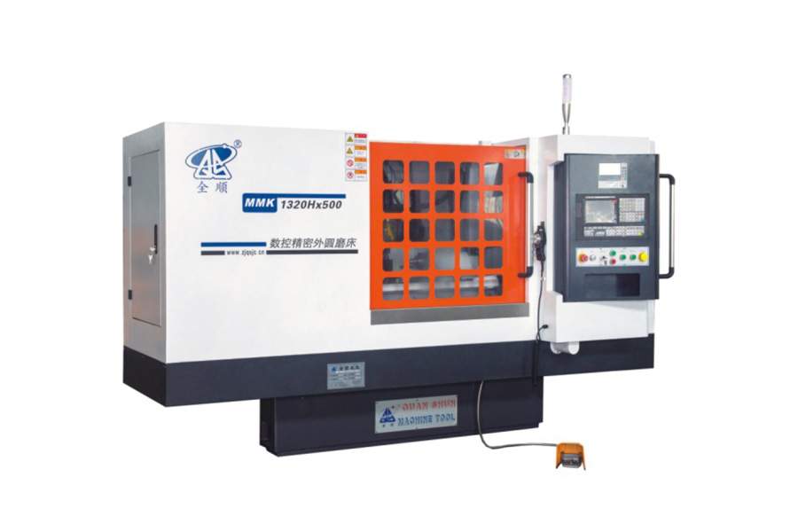
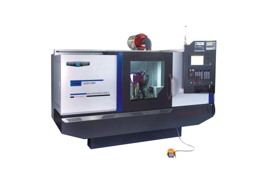
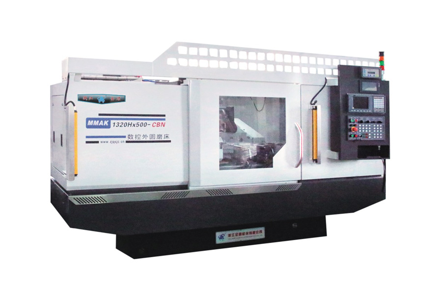
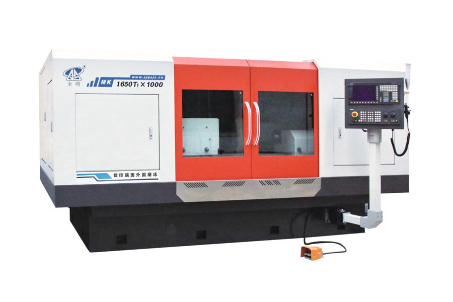
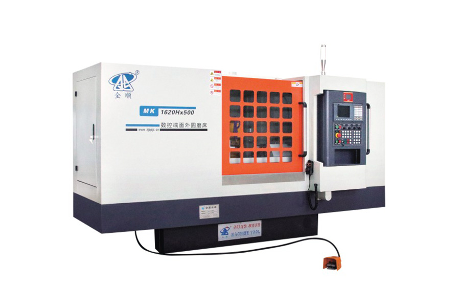
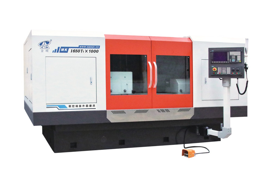
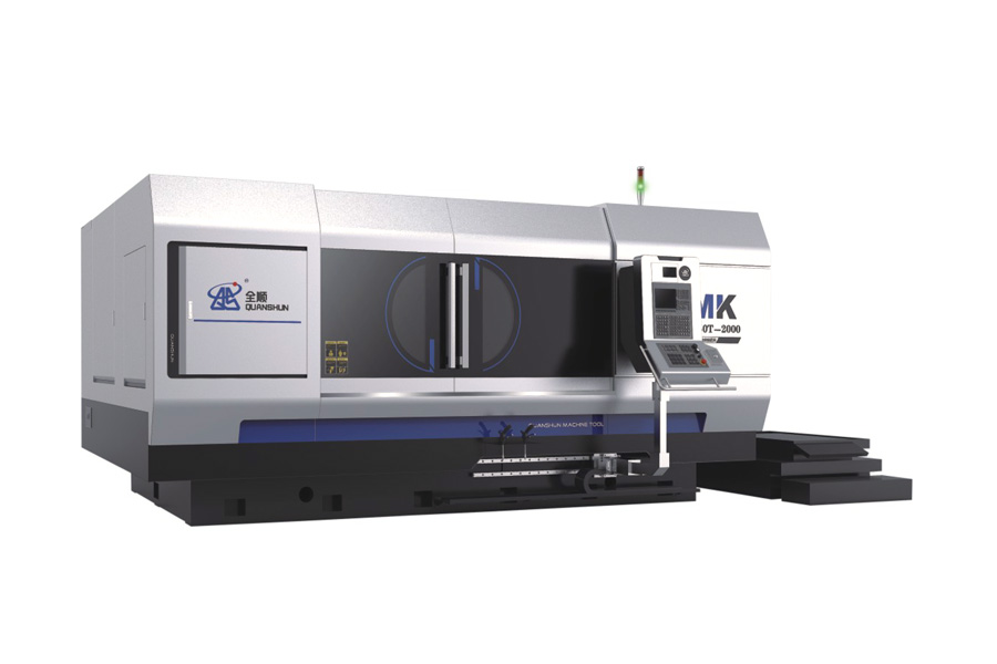
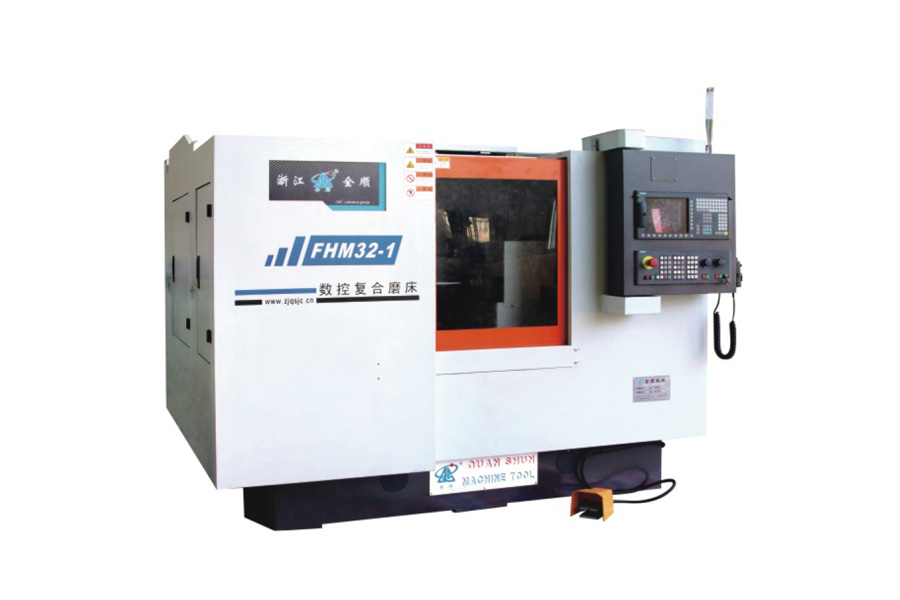
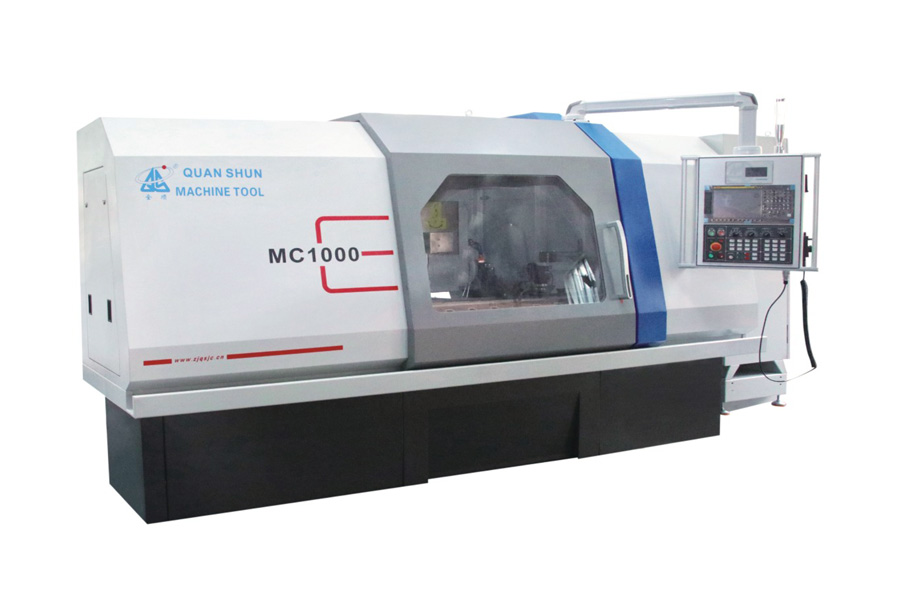
When the part geometry prevents centerless support, a high-precision CNC cylindrical grinding machine holds the same finish range while giving you the flexibility to grind several diameters, tapers, and faces in one program. The decision is not about one process being better than the other; it is about supporting the part correctly. A part that is not supported correctly will never hold a consistent finish, no matter how carefully the wheel is dressed.
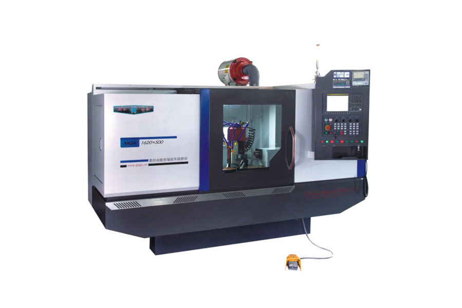 Wholesale High Precision CNC Cylindrical Grinding Machine Manufactures, FactoryAs a China High Precision CNC Cylindrical Grinding Machine manufacturer and High Precision CNC Cylindrical Grinding Machine factory, Zhej...View Product →
Correcting the most common finish defects
When a finish problem appears, work through the causes systematically rather than changing the wheel at once. The table below lists the defects most often seen in centerless grinding and their typical causes. Many of these situations are discussed in more detail in our review of common problems in centerless grinding.
| Defect | Typical causes |
|---|---|
| Burn marks or discoloration | Wheel too hard for the material, work speed too high, insufficient coolant flow |
| Chatter marks or waviness | Regulating wheel out of balance, incorrect blade height, machine vibration |
| Spiral or screw lines | Dressing feed too fast, worn diamond, wheel edge breaking down |
| Random scratches | Contaminated coolant, dirty work rest blade, swarf recirculation |
Check the obvious causes first. Most finish defects in centerless grinding come from maintenance and setup details rather than from the machine's capability. Use a short checklist before every setup change:
- Verify coolant cleanliness and nozzle position against the contact zone.
- Inspect the work rest blade for wear, nicks, or built-up swarf.
- Confirm the dressing feed rate and the condition of the diamond.
- Check the regulating wheel for balance and the work rest blade for correct height.
A structured checklist like this catches the cause quickly and brings the process back to the 16 to 4 microinch Ra range where centerless grinding belongs.