0086-15068518279 (Chinese)/001-5416026691 (English)



 EN
EN
 中文简体
中文简体Content
- 1 Typical Tolerance Ranges by Application
- 2 Key Factors That Determine Accuracy
- 3 Through-Feed vs. In-Feed vs. End-Feed: Accuracy Comparison
- 4 Common Accuracy Problems and How to Fix Them
- 5 How Centerless Grinding Compares to Other Precision Processes
- 6 Practical Steps to Maximize Centerless Grinding Accuracy
- 7 Conclusion: Setting Realistic Accuracy Expectations
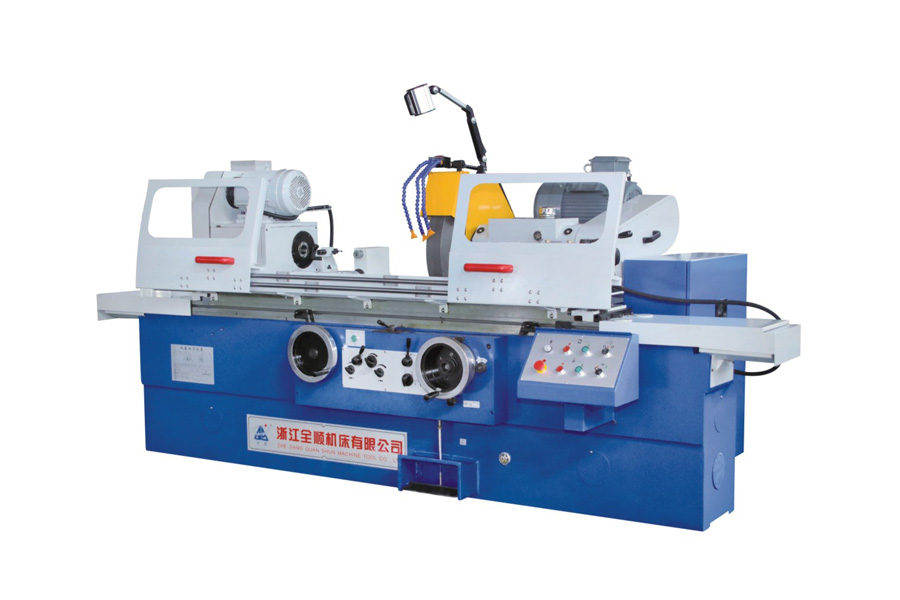
Centerless grinding is one of the most precise cylindrical machining processes available. Under well-controlled conditions, it can achieve dimensional tolerances as tight as ±0.0001 inches (±2.5 microns) and surface finishes of Ra 0.1–0.4 µm (4–16 µin). Roundness (circularity) can be held to within 0.0001–0.0003 inches depending on machine condition, workpiece material, and process setup. These figures make it suitable for precision shafts, bearing races, fuel injector components, and medical implants where tight tolerances are non-negotiable.
That said, accuracy is not automatic. It depends heavily on machine rigidity, wheel dressing, workblade angle, and material consistency. Understanding each factor helps engineers extract the full potential of the process.
Typical Tolerance Ranges by Application
Accuracy expectations vary significantly by industry and component type. The table below summarizes realistic tolerance windows achievable with properly maintained equipment and experienced operators:
| Application | Diameter Tolerance | Surface Finish (Ra) | Roundness |
|---|---|---|---|
| General industrial shafts | ±0.001 in (±25 µm) | 0.8–1.6 µm | 0.001 in |
| Automotive components | ±0.0005 in (±12.5 µm) | 0.4–0.8 µm | 0.0003 in |
| Bearing races & rollers | ±0.0002 in (±5 µm) | 0.2–0.4 µm | 0.0001 in |
| Medical implants & surgical tools | ±0.0001 in (±2.5 µm) | 0.1–0.2 µm | <0.0001 in |
| Fuel injector pins | ±0.0001 in (±2.5 µm) | 0.1–0.3 µm | 0.0001 in |
These figures assume carbide-dressed grinding wheels, flood coolant, and stable thermal conditions. Exceeding these tolerances without addressing process stability is unrealistic.
Key Factors That Determine Accuracy
Centerless grinding accuracy is the product of multiple interacting variables. Optimizing one while neglecting others will limit overall precision.
Workblade Height and Angle
The workblade positions the part between the grinding wheel and regulating wheel. Setting the work center above the wheel centerline by approximately 1/4 of the workpiece diameter is a common starting guideline. Too low causes chatter and lobing; too high reduces stock removal and can cause vibration. A blade angle of 30° is standard for most round workpieces, though angles between 25°–45° are used depending on diameter and material. Even a 1–2° error in blade angle can shift roundness by several tenths of a thousandth of an inch.
Wheel Condition and Dressing Frequency
A worn or glazed grinding wheel is one of the most common causes of tolerance drift. Grinding wheels should be redressed at regular intervals — in high-volume production, this may mean every 200–500 parts depending on material hardness. Diamond roll dressing generates the sharpest, most consistent wheel profile and is preferred for tolerances tighter than ±0.0003 inches. Single-point dressing is acceptable for roughing passes but introduces more variability.
Regulating Wheel Speed and Geometry
The regulating wheel controls workpiece rotation speed and axial feed rate. In through-feed grinding, the regulating wheel is tilted at an angle (typically 1°–5°) to generate axial workpiece movement. Small changes in this angle directly affect both feed rate and surface finish. Regulating wheel surface speed typically runs between 15–100 RPM for precision work, with lower speeds favoring tighter diameter control.
Thermal Stability and Coolant Management
Heat expansion is a major enemy of precision. A steel shaft expanding by just 1°C will grow approximately 12 µm per meter of length. Flood coolant at a consistent temperature (typically 20°C ±1°C) is essential for sub-micron accuracy. Some facilities use chilled coolant systems and allow machines to warm up for 30–60 minutes before running tight-tolerance parts.
Machine Rigidity and Spindle Condition
Vibration transmitted through the machine structure directly translates into surface waviness and diameter inconsistency. Precision centerless grinders use hydrostatic or hydrodynamic spindle bearings with radial runout below 0.0001 inches. Worn roller bearings, loose slides, or inadequate machine foundations can increase diameter scatter by 3–5× compared to a well-maintained machine.
Through-Feed vs. In-Feed vs. End-Feed: Accuracy Comparison
The grinding method chosen affects achievable accuracy:
- Through-feed grinding is best for simple cylindrical parts (constant diameter). High throughput, but diameter consistency depends on regulating wheel angle stability. Typical tolerance: ±0.0003–0.001 in.
- In-feed (plunge) grinding suits parts with shoulders, tapers, or complex profiles. Slower cycle time, but allows tighter diameter control: ±0.0001–0.0002 in on finished passes.
- End-feed grinding is used for tapered workpieces. Accuracy is slightly lower than in-feed for straight diameters but is the only practical option for tapers.
For maximum precision, in-feed grinding with a fine finishing pass (light infeed of 0.0002–0.0005 in) and a spark-out dwell of 2–5 seconds consistently delivers the tightest results.
Common Accuracy Problems and How to Fix Them
Even well-set-up machines can develop accuracy issues. Here are the most common problems and their corrective actions:
| Problem | Likely Cause | Corrective Action |
|---|---|---|
| Out-of-round (lobing) | Workblade too low | Raise workblade height; increase regulating wheel speed |
| Diameter drift over batch | Thermal expansion or wheel wear | Check coolant temperature; dress wheel more frequently |
| Poor surface finish (chatter marks) | Vibration or glazed wheel | Redress wheel; check spindle bearings; reduce feed rate |
| Taper on finished part | Wheels not parallel; regulating wheel misaligned | Re-align wheels; re-dress regulating wheel |
| Inconsistent diameter part-to-part | Incoming stock variation or unstable work rest | Increase stock removal allowance; check workblade wear |
How Centerless Grinding Compares to Other Precision Processes
Centerless grinding occupies a specific niche in the precision machining landscape. Compared to alternatives:
- vs. CNC turning: CNC turning typically holds ±0.001–0.002 in. Centerless grinding achieves 5–20× tighter diameter tolerances and far superior surface finish without workholding distortion.
- vs. cylindrical (center) grinding: Center grinding can match centerless accuracy but requires fixturing (centers or chucks), which introduces runout. Centerless avoids this — there is no fixture error because the workpiece self-locates on the blade and regulating wheel.
- vs. honing: Honing achieves comparable or better bore tolerances but is applied to internal surfaces. For external diameters, centerless grinding is generally faster and more cost-effective.
- vs. lapping: Lapping can achieve sub-micron accuracy but is extremely slow and batch-limited. Centerless grinding offers a much higher throughput for equivalent precision on cylindrical parts.
Centerless grinding's major advantage is combining high throughput with precision — a production centerless grinder can process hundreds of parts per hour while holding ±0.0002 in, something no other cylindrical process matches at that volume.
Practical Steps to Maximize Centerless Grinding Accuracy
For engineers and machinists aiming to push tolerance capability, the following practices consistently deliver results:
- Establish a consistent warm-up routine. Allow the machine to run for at least 30 minutes with coolant flowing before taking in-process measurements on critical parts.
- Control incoming stock diameter variation. If bar stock varies by ±0.005 in, the grinder must remove enough material to correct it — which increases wheel wear and heat. Specifying tighter raw stock reduces process burden.
- Use a finishing wheel with a fine grit. Roughing with a 46–60 grit wheel and finishing with a 120–220 grit wheel in separate passes dramatically improves surface finish without sacrificing cycle time.
- Implement Statistical Process Control (SPC). Measuring every 10th–25th part and charting Xbar-R data reveals trends before they produce scrap. A Cpk above 1.33 is a standard benchmark for production approval.
- Inspect workblades regularly. Worn blades change the workpiece support geometry and shift diameter. Replacing blades on a scheduled interval — not just when problems arise — avoids tolerance excursions.
Conclusion: Setting Realistic Accuracy Expectations
Centerless grinding is capable of exceptional precision — ±0.0001 in diameter tolerance and Ra 0.1 µm surface finish under optimized conditions. However, real-world accuracy is defined by the weakest link in the process chain: machine condition, setup discipline, coolant control, and material consistency all play equal roles.
For most production applications, a well-maintained centerless grinder reliably delivers ±0.0002–0.0005 in on diameter with surface finishes in the 0.2–0.8 µm Ra range — accuracy that meets or exceeds the requirements of the vast majority of precision cylindrical components in automotive, aerospace, and medical manufacturing.