0086-15068518279 (Chinese)/001-5416026691 (English)



 EN
EN
 中文简体
中文简体Content
- 1 OD Grinding and ID Grinding Are Not the Same Operation
- 2 What Tolerances and Finishes Are Realistic
- 3 Universal Grinders and the One-Setup Question
- 4 Matching the Machine to the Part Family
- 5 Process Parameters That Decide the Outcome
- 6 A Checklist Before You Specify the Machine
- 7 Where OD and ID Grinding Projects Usually Go Wrong
A job shop turns a batch of hardened 40Cr shafts, then moves them across the aisle to the grinder because the print calls for h6 on the outside diameter, H7 on a 40 mm bore, and 0.02 mm concentricity between the two. Turning can hold the size on a good day. It will not hold the roundness, and it will not touch the finish.
The short answer before the detail: OD grinding and ID grinding are two separate operations with different kinematics, wheel limits, cooling behaviour and fixturing. The feature that carries your tightest tolerance should decide which machine you buy. The other feature can usually be handled in a second operation, on a second machine, or with an attachment that is chosen deliberately rather than by default.
OD Grinding and ID Grinding Are Not the Same Operation
In OD grinding, the workpiece is held between centres or in a collet chuck and rotates while the wheel works from the outside. Wheel surface speed typically runs 30 to 45 m/s on a vitrified wheel, work speed sits around 20 to 40 m/min, and the contact zone is short, open and easy to flood with coolant. Stiffness is high because the wheelhead is supported close to the grinding point.
ID grinding inverts that geometry. The wheel has to fit inside the bore, so its diameter is capped, often at 60 to 80 percent of the bore diameter. For the same spindle speed, that means lower wheel surface speed and a longer contact arc for every unit of material removed. Heat concentrates in a thinner wall section, chips and coolant must escape through a smaller opening, and the quill carrying the wheel is less rigid than a conventional wheelhead. Once the depth-to-diameter ratio passes roughly 3:1, coolant starvation and quill deflection start to appear directly in the roundness trace.
Neither operation is harder in absolute terms. They fail in different ways. That is why most external work runs comfortably on OD grinding machines built around external grinding geometry, while internal work rewards a machine designed for it rather than adapted to it.
| Aspect | OD Grinding | ID Grinding |
|---|---|---|
| Wheel position | Outside the workpiece | Inside the bore |
| Wheel diameter | 400 to 600 mm typical | Capped by bore size |
| Contact arc | Short, open | Long relative to stock removed |
| Coolant access | Easy to flood | Restricted as depth increases |
| Typical grade held | IT5 to IT6 | IT7 to IT8 |
| Typical roughness | Ra 0.1 to 0.4 µm | Ra 0.4 to 0.8 µm |
| Main risks | Roundness, taper, chatter | Heat, deflection, wheel loading |
What Tolerances and Finishes Are Realistic
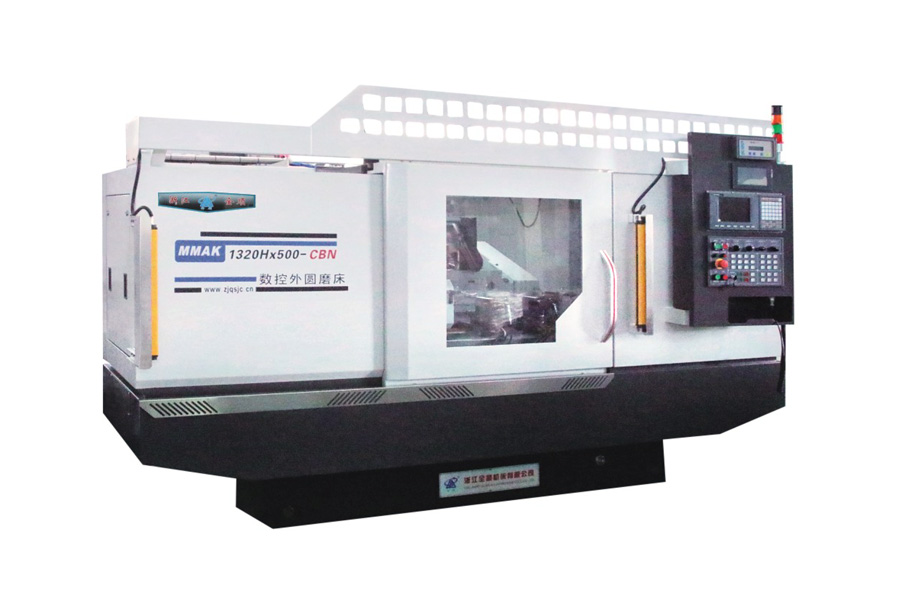
On a properly set-up CNC cylindrical grinding machine with in-process gauging, OD grinding commonly holds IT5 to IT6, roundness in the 1 to 2 µm band, and a surface finish of roughly Ra 0.1 to 0.4 µm. ID grinding on a general-purpose machine usually lands in the IT7 to IT8 range with Ra 0.4 to 0.8 µm. Tighter than that inside a bore is achievable, but it calls for a high-frequency internal spindle, lighter stock removal, a longer spark-out stage and a structure designed around internal work.
Concentricity deserves its own line in the enquiry. If the print asks for 0.02 mm between the bore and the OD, grinding both features in a single chucking removes fixture error from the tolerance stack. Two separate setups require a driver or fixture that repeats within a few microns, and that requirement shapes the machine architecture, not just the process sheet.
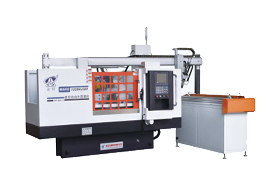
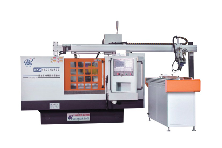
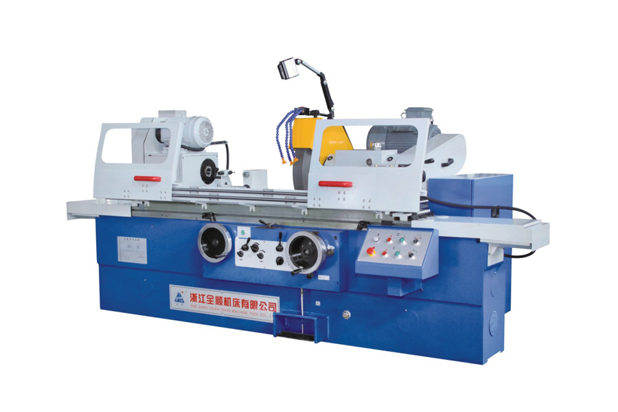
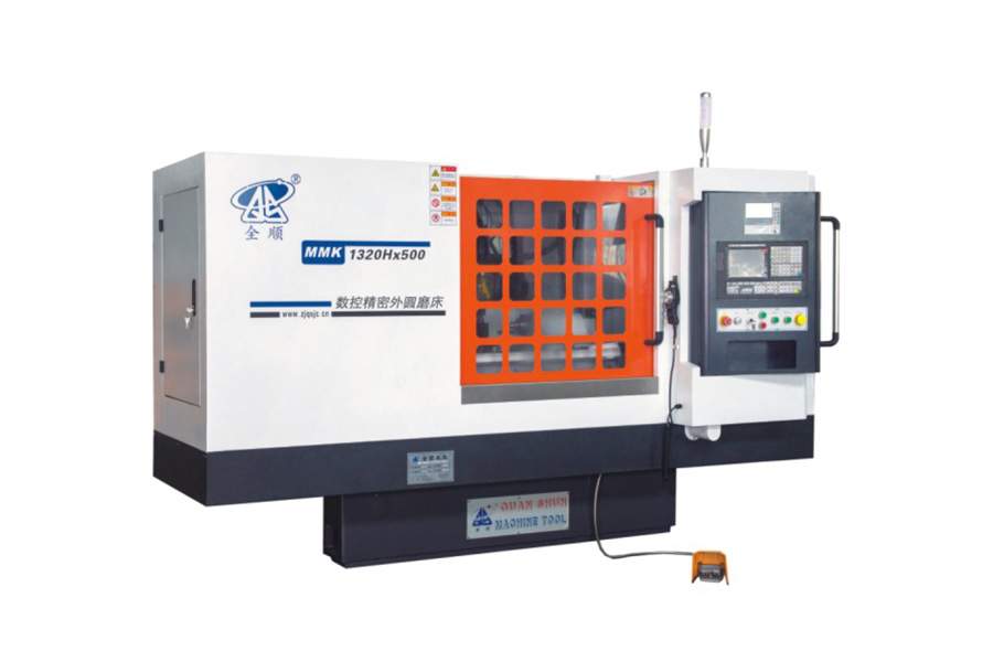
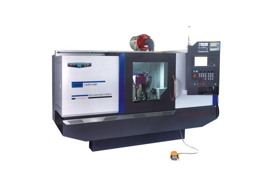
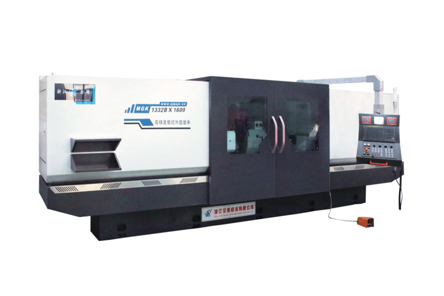
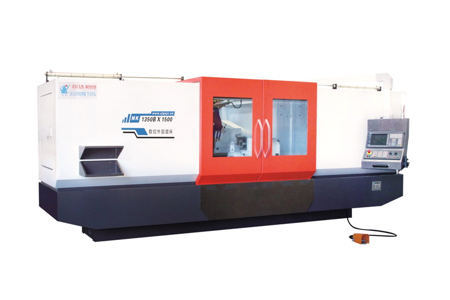
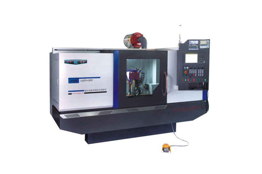 High Precision CNC Cylindrical Grinding Machine SeriesReview this external cylindrical grinder when tight concentricity and repeating batches demand thermal stability, fine infeed resolution, and reliable multi-step shaft grinding.View Product →
Where the tolerance band is genuinely tight and the batch repeats, a high-precision platform with thermal stability and fine infeed resolution is usually cheaper over three years than a standard machine plus rework.
Universal Grinders and the One-Setup Question
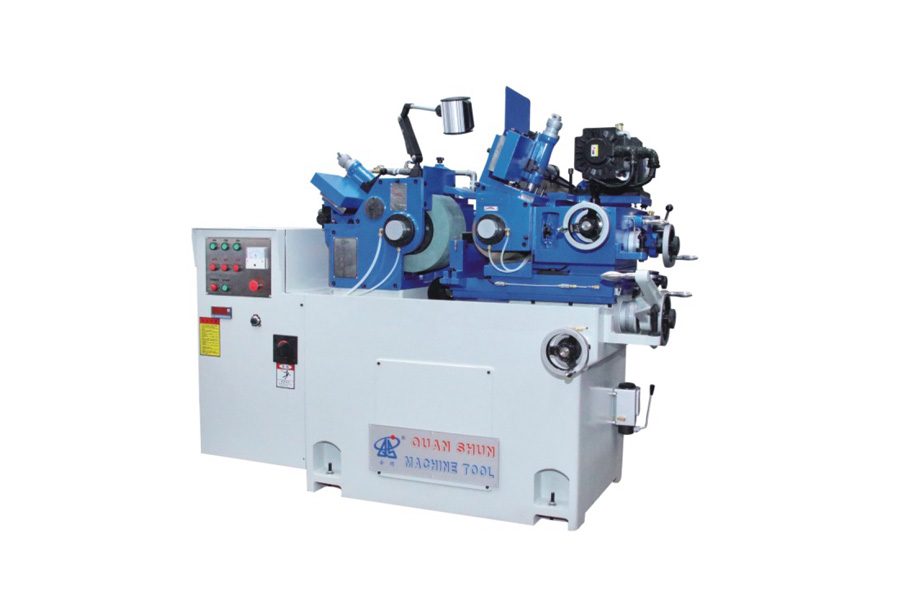
A universal cylindrical grinder with a swivelling worktable and an internal grinding attachment can handle both the OD and the bore on one platform. For a job shop running mixed, low-volume work, that flexibility is often worth more than the last micron of productivity.
The compromise is real, though. Internal attachments on universal machines generally run at lower spindle speeds than dedicated internal spindles, the internal wheel is small, and every switch between external and internal work costs changeover time plus a re-dress and a re-check of alignment. A practical rule: if the internal work is under about 20 percent of cycle time, and the bores are larger than 30 mm with a depth-to-diameter ratio under 2:1, an attachment on a universal platform is efficient. If the bores are small, deep, or carry the tightest tolerance on the print, separate the operations.
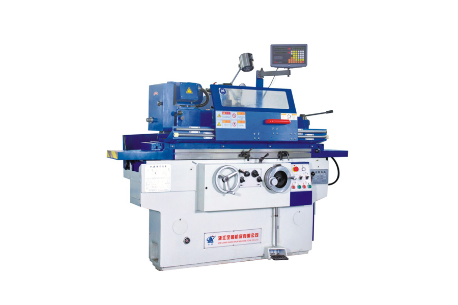
 CNC Universal Cylindrical Grinding MachineReview this universal cylindrical grinder for mixed OD and ID work, with a swiveling wheelhead enabling external and internal grinding in one setup.View Product →
Matching the Machine to the Part Family
Most OD and ID work falls into recognisable families, and each family pushes the specification in a different direction.
- Shafts and pins with centre holes: a CNC cylindrical grinder with plunge or traverse cycles covers the majority of sizes.
- Small cylindrical parts without centre holes, produced in volume: centreless grinding removes the centres entirely and supports the part on a regulating wheel and work rest.
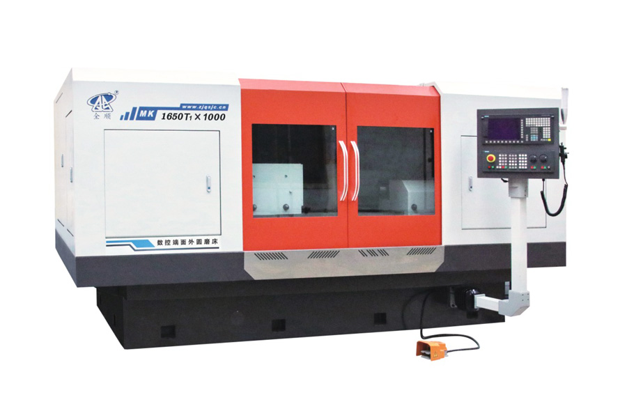
- Flanged parts needing an OD and a shoulder face in one setup: a face and cylindrical grinder with a swivelling wheelhead does both without a second clamping.
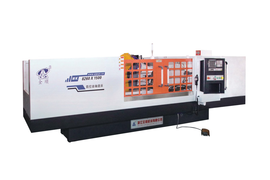
- Eccentric or offset journals: a follow-type crankshaft grinder tracks the rotating centreline instead of relying on an eccentric fixture.
- Bores that dominate the print: dedicated internal grinding capacity, not an attachment, sets the achievable roundness and finish.
For parts that arrive without a centre hole and cannot be chucked repeatably, centreless grinding is often the difference between a stable process and a permanent fight with runout.
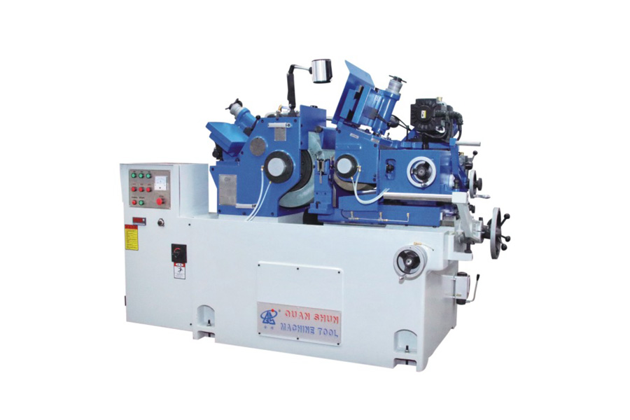 High-Speed Precision Centerless Grinding MachineFor parts without center holes that cannot be chucked repeatably, this centerless grinder supports stable thru-feed or plunge grinding with roundness and finish control.View Product →
Process Parameters That Decide the Outcome
Once the machine is on the floor, a handful of parameters determine whether the process holds tolerance across a shift or drifts after the first fifty parts.
- Wheel and work speed ratio. Adjusting the ratio changes chip thickness and burn risk far more than adjusting the infeed alone.
- Infeed and spark-out. A short spark-out stage leaves size and roundness moving after the infeed stops, which shows up as scatter within a batch.
- Dressing interval and method. Dressing too late loads the wheel and raises temperature; dressing too often wastes wheel life and adds cycle time.
- Coolant delivery. For internal work, nozzle position and pressure matter more than total flow, because heat reaches the work through the contact arc.
- Gauging and temperature stabilisation. Measuring hot parts is one of the most common causes of a stable process appearing to drift.
A Checklist Before You Specify the Machine
Bring these numbers to the table and the machine conversation becomes short and factual.
- Maximum and minimum OD, bore diameter, bore depth and depth-to-diameter ratio.
- Which feature carries the tightest tolerance, and the concentricity requirement between them.
- Workpiece material and hardness, plus any thin-wall or interrupted sections.
- Batch size, cycle time target and whether manual or automatic loading is acceptable.
- Required roundness, cylindricity and surface roughness, stated numerically rather than as "mirror finish".
- Available floor space, foundation and power supply, since machine mass affects vibration behaviour.
- Gauging method, expected repeatability and how the gauge will be calibrated.
- Service access, spare wheel supply and operator training needs.
Where OD and ID Grinding Projects Usually Go Wrong
The failures are repetitive and almost always identifiable before the machine is ordered.
- Thermal growth is ignored. Wheelhead, coolant and ambient temperature interact, and an unstable room temperature can account for more dimensional drift than the machine itself.
- Thin-wall parts are clamped as if they were solid. The bore springs back after unclamping and the roundness fails at inspection.
- The wheel is chosen for the machine rather than the material. Soft or sticky alloys load a wheel that works perfectly well on hardened steel.
- The specified finish cannot be measured reliably on the shop floor, so acceptance depends on whoever inspects that day.
- Internal work is treated as an afterthought, and the attachment becomes the bottleneck for the whole cell.
OD and ID grinding sit at the end of the value chain for most round parts, which means every decision in the process is visible in the finished component. Get the tolerance stack right first, decide whether external and internal work belong on one platform or two, and then specify speed, stiffness and gauging around the feature that actually governs acceptance. That sequence keeps a grinding project inside budget and keeps the process stable long after the commissioning engineer has gone home.