0086-15068518279 (Chinese)/001-5416026691 (English)



 EN
EN
 中文简体
中文简体Content
- 1 Flatness and Level Are Two Different Numbers
- 2 Typical Foundation Flatness Tolerances by Equipment Type
- 3 What a Flatness Error Does to a Grinding Machine
- 4 How Flatness Is Tested Before the Machine Is Set
- 5 Common Mistakes and Realistic Fixes
- 6 Writing the Flatness Requirement Into the Specification
- 7 Matching Machine Class to What the Foundation Can Hold
Most foundation problems in a grinding shop are discovered the same way. The machine is leveled, the first trial part is ground, and the taper or roundness reading does not match what the machine is supposed to hold. The pad looked flat, it was level, and it still was not flat enough.
Flatness is the departure of the pad surface from a true plane. It is the reference that everything downstream is measured against: bed twist, slide straightness, wheelhead and workhead alignment, and finally the tolerance on the part. Level only tells you whether the pad sits horizontal.
The conclusion comes first. Specify local pad flatness both as a rate in mm/m and as a total deviation in millimetres across the machine footprint, measure it before the machine is set, and treat the figure in the machine installation manual as the acceptance criterion rather than the building slab specification.
Flatness and Level Are Two Different Numbers
A precision level is a fine instrument, but in one position it cannot tell you whether a pad is twisted. Readings taken along one axis, then the perpendicular axis, then diagonally can all look acceptable while the surface still warps in the middle by a millimetre or two. Level describes the angle of a surface relative to horizontal. Flatness describes how far the surface departs from a true plane. A pad can be perfectly level and still be twisted, and it can be flat but slightly tilted, which is usually harmless if the machine is leveled on its own feet.
Flatness is normally written in two ways: as a rate, such as 0.02 mm per metre, or as a total deviation, such as 0.1 mm across a 3 m pad. The rate is useful when checking a machine bed for twist. The total deviation matters more when checking whether a base with four feet will sit without being pulled out of shape.
There is also a scale problem. Floor specifications such as ACI 117 describe a slab statistically through FF and FL numbers, measured with a floor profilometer over short increments. A machine foundation requirement is local: how flat the pad is under one base, over one footprint, and whether every foot will touch. A slab can pass a good FF number and still have a high spot of two or three millimetres inside the footprint. That gap produces most installation arguments.
Typical Foundation Flatness Tolerances by Equipment Type
The figures below are indicative values taken from common installation practice. They do not replace the machine manual, which is the document that decides acceptance on site.
| Equipment | Typical target | What it protects |
|---|---|---|
| CNC cylindrical grinder, standard class | Level within 0.02 mm/m both axes; local deviation under 0.05 mm across the footprint | Bed twist, taper, roundness |
| High-precision or compound grinder | 0.01 to 0.02 mm/m; full contact under every leveling point | Roundness, surface finish, long-term geometry |
| Surface grinder | 0.02 to 0.04 mm/m | Table travel, parallelism of ground faces |
| CNC lathe or turning centre | 0.02 to 0.05 mm/m | Spindle alignment, chatter |
| Crankshaft or large calibre grinder | Thicker pad; local deviation under 0.1 mm over a longer footprint | Dynamic loads, uneven wear of the base |
| Pump or skid baseplate | 0.05 to 0.1 mm across the baseplate, per the maker | Coupling and bearing life |
| General industrial slab to ACI 117 | FF 25 / FL 20 typical for traffic floors | Traffic and racking, not machine geometry |
Note the order of magnitude between the bottom row and the machine rows. A warehouse floor that satisfies the building specification can still be two orders of magnitude coarser than what a precision grinder base needs locally. That is why a machine foundation drawing is written around the footprint and the base casting, not around the whole slab area.
What a Flatness Error Does to a Grinding Machine
Twist is the most common result. If a cylindrical grinder bed is twisted by 0.02 mm over a 1 m length, the workhead and wheelhead no longer travel in the same plane. Grinding a 300 mm shaft on that machine can leave measurable taper, and the operator will chase it with wheel dressing, feed changes and re-clamping that never quite solve it. The foundation was the cause, and the symptom appears two steps downstream.
Soft foot is the second. A foot sitting above the pad pulls the bed down when the anchor bolt is tightened, and the bed deflects. Levels taken after tightening read differently from levels taken before, and the geometry changes again once coolant, workpiece and clamping loads are added.
Contact condition is the third. A machine standing on three effective points instead of the full pad has a dynamic response different from the one the builder tested. The result is chatter, a surface finish that will not repeat, or a wheel that wears unevenly.
Machine class decides how much of this can be absorbed. A machine built for precision work carries tighter foundation requirements than the same size machine in a standard build, and the manual will state them.
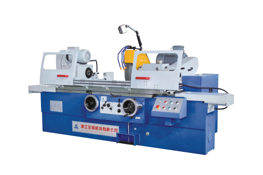
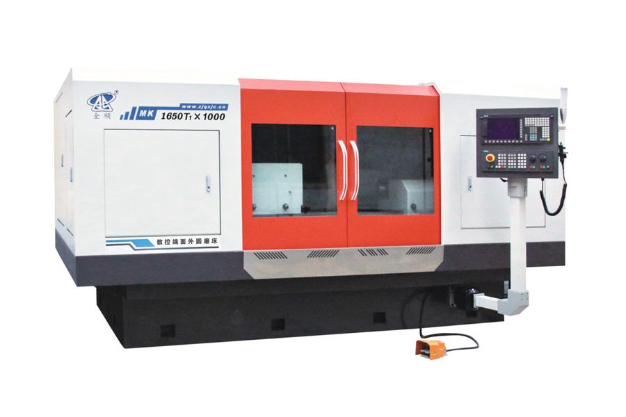
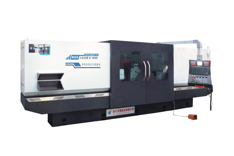
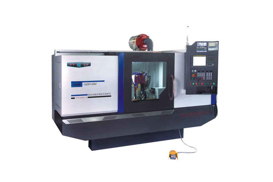 High Precision CNC Cylindrical Grinding MachineFor precision external grinding, this machine combines a Meehanite cast iron bed, sub-micron feeding, and CNC control for cylindrical, tapered, and multi-step shafts.View Product →
How Flatness Is Tested Before the Machine Is Set
- Straightedge and feeler gauge, as a fast first look at local high spots under each foot position.
- Precision machinist level or electronic level at 0.02 mm/m resolution or finer, read along both axes and on the diagonals.
- Dial indicator on a granite or steel straightedge, used to map the pad in a grid.
- Floor profilometer, when the FF and FL numbers of the whole slab are in question.
- Laser tracker or interferometer, for long spans or a line of pads that must share one reference.
- Autocollimator with a moving reflector, where a straightedge is impractical.
Sequencing matters more than the instrument. Measure after the concrete has cured and the grout has hardened, not on the day the pad is poured. Map the surface on a grid of roughly 300 mm and record the maximum deviation and its position rather than a single average. Re-check after the machine has stood under its own weight for 24 to 72 hours, and again after the first production run, because a pad that settles will move.
If a machine is being prepared for commissioning, the installation sequence is worth reading before the pad is poured, not after. A checklist covering foundation, power and leveling checks is a cheap way to avoid a second concrete job.
Common Mistakes and Realistic Fixes
Six mistakes account for most flatness failures:
- Testing the structural slab when the machine pad is a separate, later pour at a different level.
- Reading flatness before curing is complete, while the concrete is still shrinking and losing moisture.
- Treating shims as permanent support instead of a setting aid, so the load never transfers to grout.
- Casting a pad smaller than the base, leaving feet overhanging the edge.
- Pouring the pad monolithically with the surrounding floor and inheriting its movement.
- Grouting onto a damp, dusty or contaminated substrate.
Fixes run from cheap to expensive. Epoxy grout injection under a baseplate restores full contact and can be done in a maintenance window. A self-leveling epoxy corrects small deviations, but only within the thickness the product allows. Diamond grinding or hydro-milling removes a local high spot. A pad that is out of tolerance across its whole footprint is usually re-poured, because no amount of shimming makes a twisted base behave like a straight one.
Writing the Flatness Requirement Into the Specification
The foundation specification is where this is either controlled or lost. Eight items are worth writing down explicitly.
- Local planarity: total deviation in millimetres across the full machine footprint, not only a rate in mm/m.
- Levelness: allowable deviation in both axes, measured after grout cure and after anchor bolts are torqued.
- Pad dimensions, thickness and edge distance, plus reinforcement and anchor bolt layout with positional tolerances.
- Grout type, minimum thickness and compressive strength, with substrate moisture limits.
- Isolation joints or separation layers between the machine pad and the surrounding slab, including trenches and cable ducts.
- Measurement method, instrument resolution and the number of measurement points.
- Cure and acceptance timing, and who signs the flatness report before the machine is set.
- The machine manual tolerance, named as the acceptance criterion, with the measured report handed over before installation begins.
Series machines usually ship with published foundation and leveling figures, so the civil contractor can be held to a number that already exists rather than one invented on site.
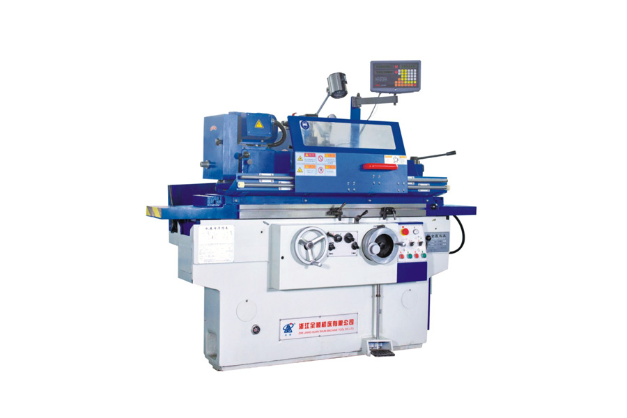
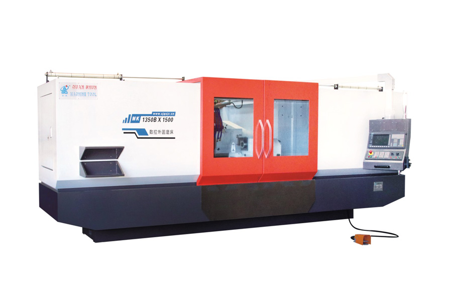
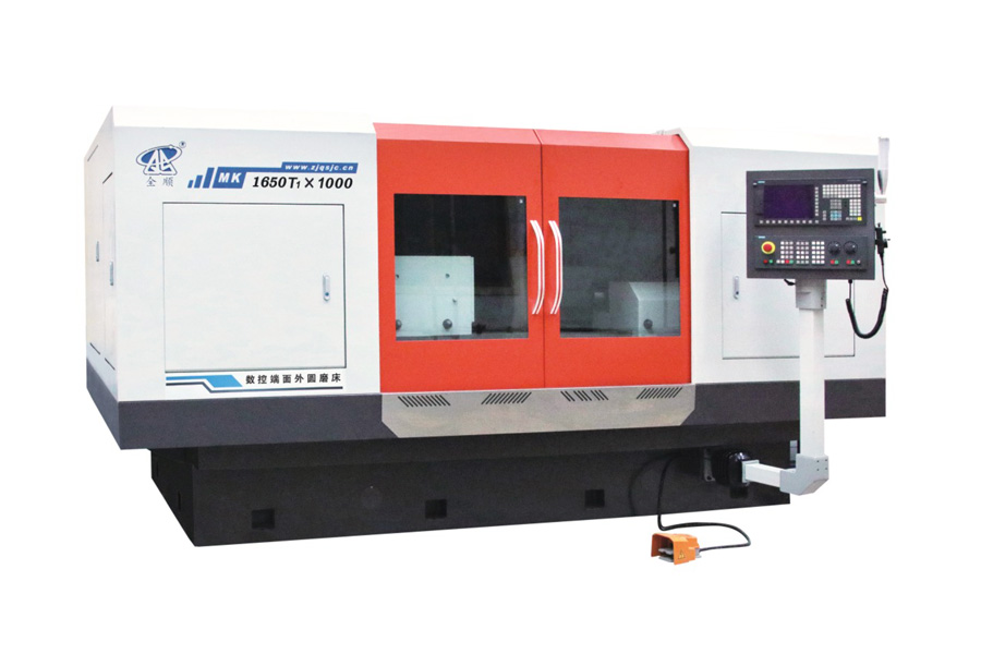
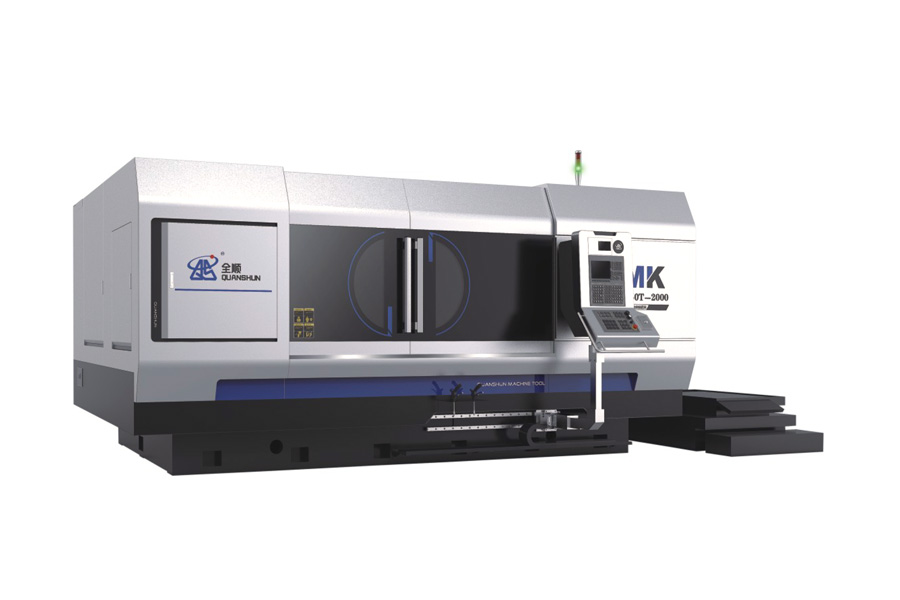
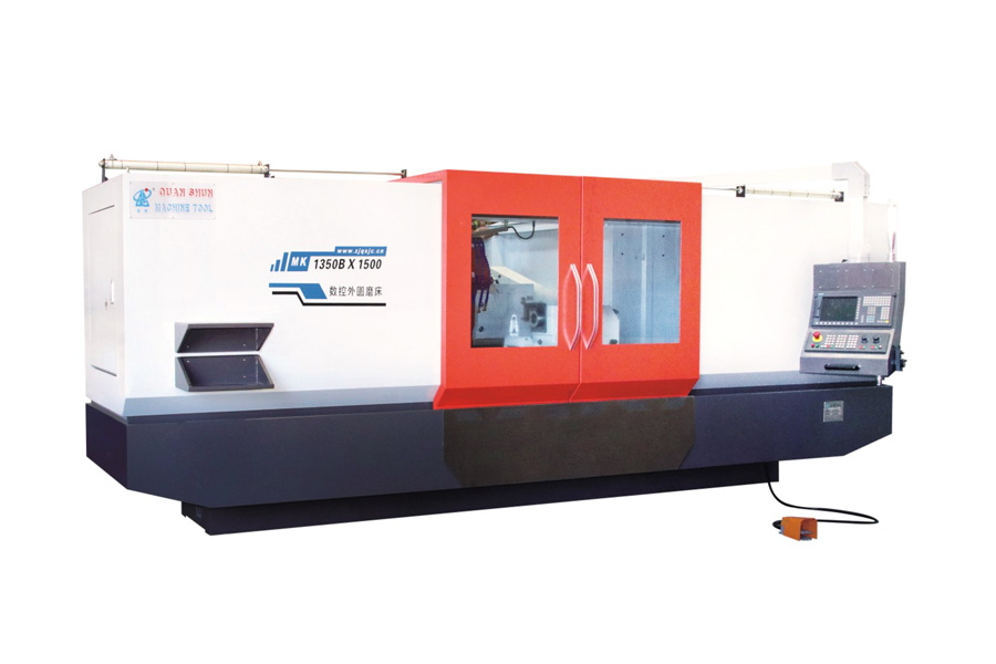 CNC Cylindrical Grinding Machine MK/MAK SeriesThis series uses rigid castings, hydrostatic or hydrodynamic bearings, and CNC integration for sub-micron repeatability in cylindrical, tapered, and multi-step shaft grinding.View Product →
Matching Machine Class to What the Foundation Can Hold
Automatic loading and unloading changes the requirement rather than removing it. A machine that loads its own workpieces runs thousands of cycles per shift, and each one depends on the relationship between the loader and the workhead staying where it was set. A pad that creeps, settles or flexes under changing load shifts that relationship slowly, and the faults look like loader problems rather than foundation problems.
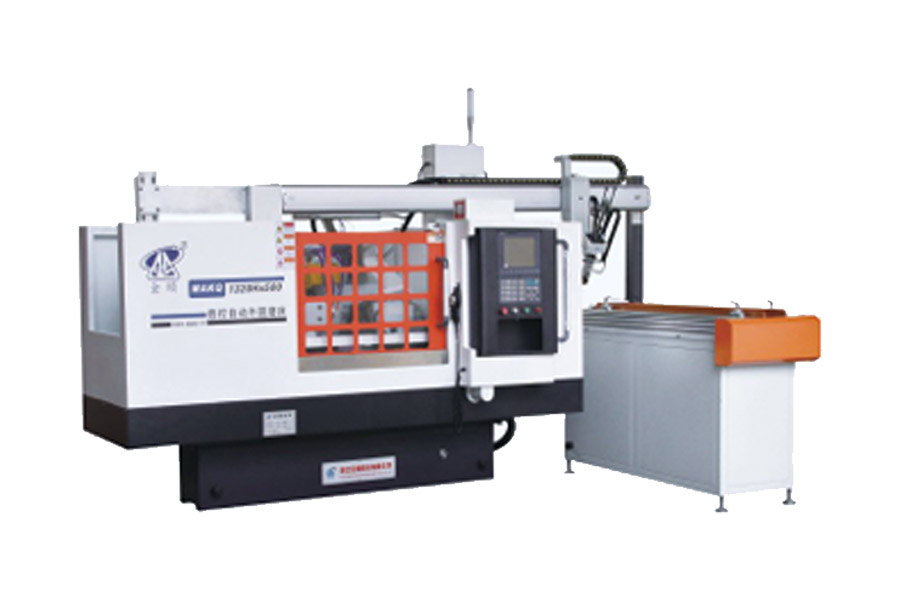
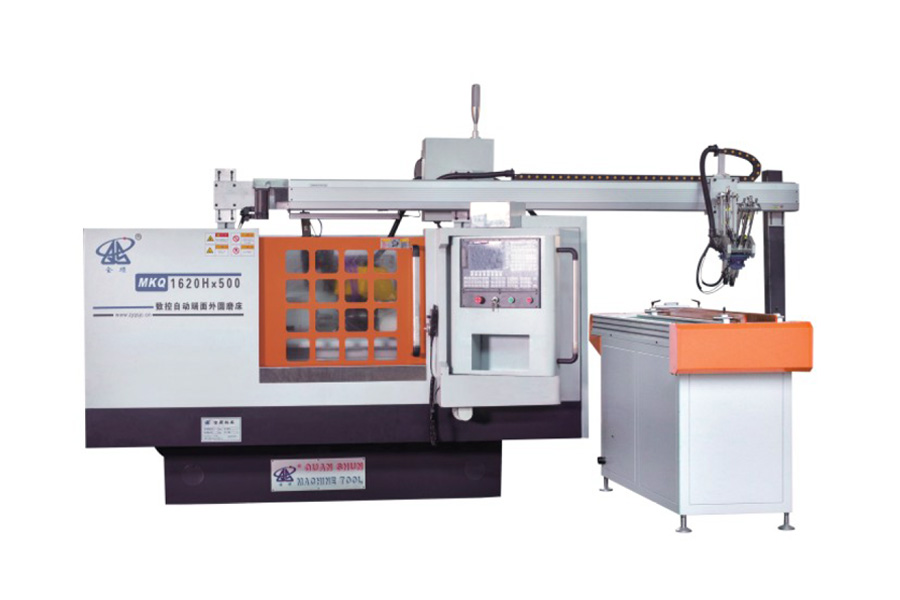
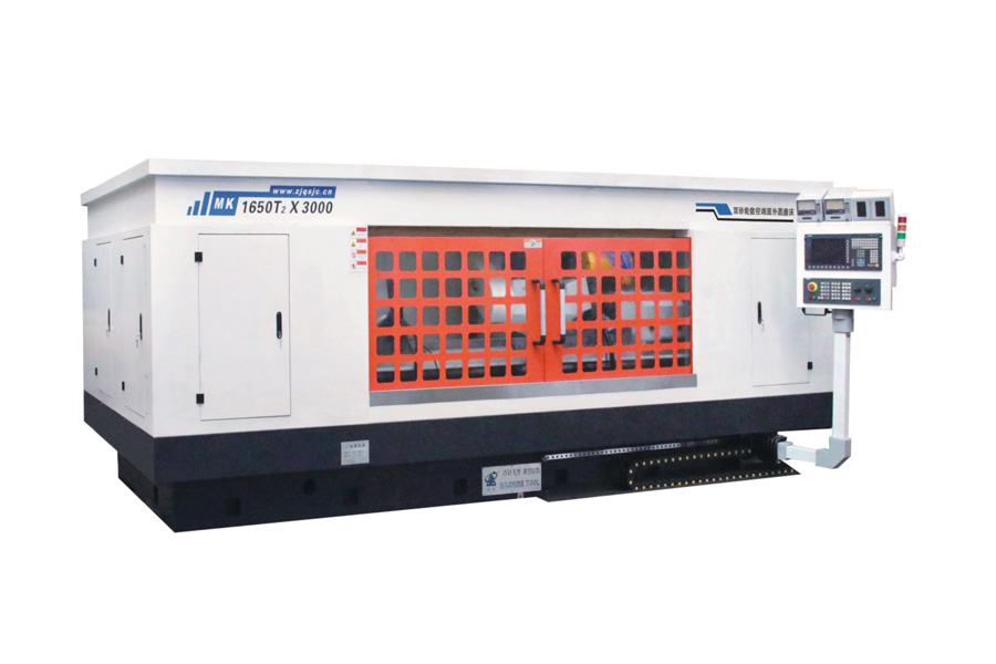
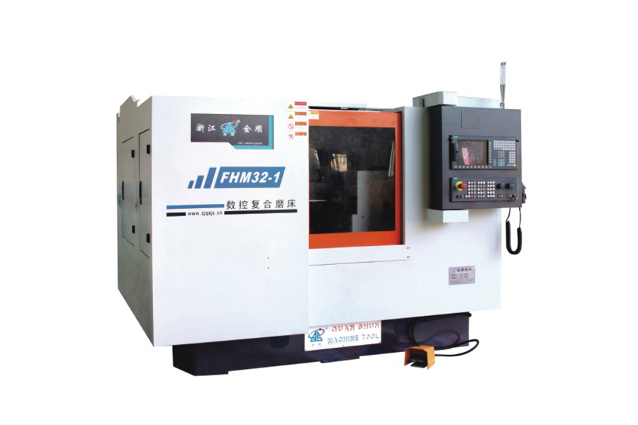
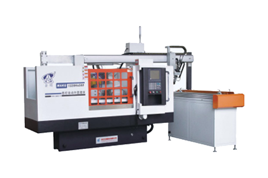 Automatic CNC Cylindrical Grinding Machine for Mass ProductionBuilt for automatic loading and unloading, this grinder supports simultaneous grinding and robotic handling, with a patented clamping system for secure, damage-free workpiece holding.View Product →
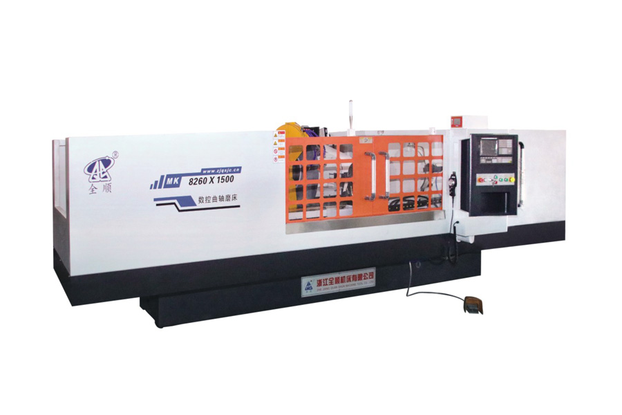
Large workpieces and heavy base castings push in the other direction. Crankshaft, large calibre and compound machines carry more mass and generate different dynamic loads, so pad area and thickness grow before the flatness figure is even discussed.
For non-standard work, the foundation stops being a generic civil item. A custom grinding machine built around an unusual workpiece, a long broach or a large diameter shaft may need a foundation drawing issued with the machine itself, because the mass distribution and the leveling points are not the same as those of a series model.
The sequence that works is short. Take the tolerance from the machine manual, write it into the civil contract as a local planarity figure in millimetres across the footprint, measure the finished pad in a grid after curing and grouting, and keep the report on file.
A foundation is the cheapest part of a grinding installation to get right and one of the most expensive to get wrong, because a flatness error is paid for every shift, in scrap parts and in adjustment time that never quite clears.