 0086-15068518279 (Chinese)/001-5416026691 (English)


 EN
EN
 中文简体
中文简体Content
- 1 What Is Centerless Grinding?
- 2 How Centerless Grinding Works: The Core Mechanism
- 3 The Three Types of Centerless Grinding
- 4 Centerless Grinding vs Cylindrical Grinding: Key Differences
- 5 Advantages of Centerless Grinding
- 6 Limitations to Be Aware Of
- 7 Materials Commonly Ground by Centerless Grinding
- 8 Industries That Rely on Centerless Grinding
- 9 Key Process Parameters That Affect Quality
- 10 When to Choose Centerless Grinding for Your Application
What Is Centerless Grinding?
Centerless grinding is a precision machining process that removes material from the outer surface of a cylindrical workpiece without mounting the part between centers or in a chuck. Instead, the workpiece is supported by a work rest blade and guided between two wheels — a grinding wheel and a regulating wheel — which simultaneously control both the cutting action and the rotational speed of the part.
The key advantage over conventional cylindrical grinding is throughput and consistency: centerless grinding can achieve tolerances as tight as ±0.0025 mm (±0.0001 in) at high production rates, making it one of the most efficient methods for finishing round parts in large volumes.
How Centerless Grinding Works: The Core Mechanism
Understanding centerless grinding starts with its three-component setup. These three elements work together to hold, rotate, and grind the workpiece without any clamping or center support.
The Grinding Wheel
This is the primary cutting tool. It rotates at high speed — typically between 30 and 60 m/s — and removes material from the workpiece surface through abrasive action. The wheel is fixed in position and sets the final diameter of the part.
The Regulating Wheel
Positioned opposite the grinding wheel, the regulating wheel rotates in the same direction as the grinding wheel but at a much slower speed. It controls the rotational speed of the workpiece and, in through-feed grinding, the axial feed rate. The regulating wheel is typically made of a rubber-bonded abrasive that grips the workpiece surface without cutting it.
The Work Rest Blade
A flat, angled blade positioned below the workpiece supports it between the two wheels. The blade is usually set slightly above the centerline of the two wheels — commonly by an amount equal to approximately half the workpiece diameter. This offset is critical: it prevents the part from chattering or being forced downward by grinding forces, and it helps maintain a consistent round form.
The interaction of these three components creates a self-centering effect. As the grinding wheel pushes the part against the regulating wheel and blade, the part continuously corrects its own roundness with each revolution — a phenomenon that makes centerless grinding particularly effective at producing highly circular parts.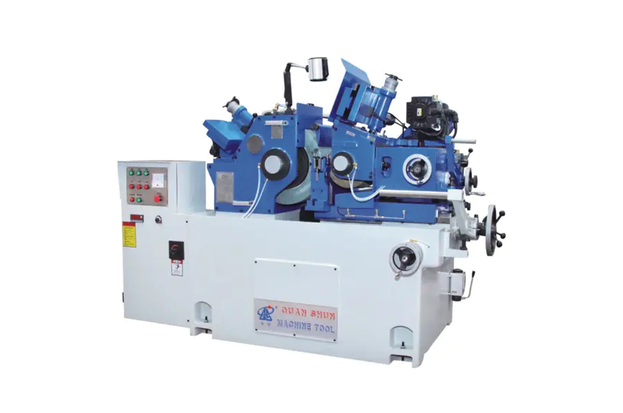
The Three Types of Centerless Grinding
There are three distinct methods of centerless grinding, each suited to different part geometries and production requirements.
Through-Feed Centerless Grinding
The workpiece is fed axially through the grinding zone from one side to the other in a continuous pass. The regulating wheel is angled slightly — typically 1° to 6° — to create the axial feed force that moves the part through the machine. This is the fastest method and is ideal for simple, straight cylindrical parts such as pins, rods, bolts, and shafts that have no steps or flanges. Production rates can reach hundreds of parts per minute for small components.
In-Feed (Plunge) Centerless Grinding
The workpiece is placed on the work rest blade and the regulating wheel is fed radially inward until the target diameter is reached. The part does not travel axially. This method is used for parts with complex profiles, shoulders, tapers, or multiple diameters — shapes that cannot pass straight through the grinding zone. A typical example is a camshaft lobe or a stepped valve stem.
End-Feed Centerless Grinding
The workpiece is fed axially into the grinding zone from one end only and stops against a fixed end stop. It is then ground to size and retracted. This method is mainly used for tapered parts, where the grinding wheel and regulating wheel are dressed to produce the required taper profile. Production rates are lower than through-feed but higher than many conventional grinding methods for tapered components.
| Comparison of the three centerless grinding methods | |||
| Method | Part Movement | Best For | Relative Speed |
| Through-Feed | Axial, continuous | Straight cylinders, high volume | Fastest |
| In-Feed (Plunge) | None (radial plunge) | Stepped, profiled, shouldered parts | Medium |
| End-Feed | Axial to stop, then retract | Tapered parts | Moderate |
Centerless Grinding vs Cylindrical Grinding: Key Differences
Both processes grind the outer diameter of cylindrical parts, but they are suited to very different situations. Choosing the wrong process for a job leads to unnecessary cost or quality problems.
| Centerless grinding compared to conventional cylindrical grinding | ||
| Characteristic | Centerless Grinding | Cylindrical Grinding |
| Workpiece support | Work rest blade + regulating wheel | Centers or chuck |
| Setup time | Longer initial setup | Faster per part |
| Production rate | Very high (continuous feed possible) | Lower, part-by-part |
| Part length limitation | None (through-feed) | Limited by machine capacity |
| Complex profiles | Limited (in-feed only) | More flexible |
| Concentricity control | Good roundness, limited concentricity | Better concentricity to datum |
| Automation potential | Very high | Moderate |
As a general rule: if you are producing large quantities of simple cylindrical parts and roundness is the primary geometric requirement, centerless grinding is the more productive choice. If the part has a critical concentricity requirement relative to a bore or datum feature, cylindrical grinding between centers offers better control.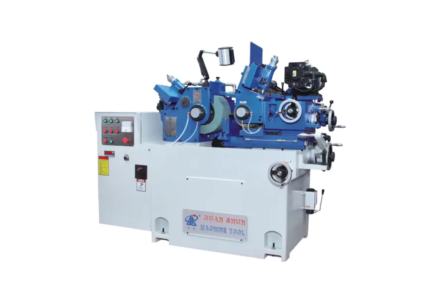
Advantages of Centerless Grinding
- High production rates: Through-feed centerless grinding can process bars, pins, and rods in a near-continuous stream, with no loading or unloading time between parts.
- Excellent roundness: The self-centering nature of the process produces very high circularity values, often better than 0.002 mm.
- No fixture-induced distortion: Because the workpiece is not clamped, there is no risk of deformation from clamping forces, which is critical for thin-walled or delicate parts.
- Consistent diameter control: Automatic sizing and in-process gauging allow diameter to be maintained within very tight bands across entire production runs.
- Handles long workpieces: Parts longer than the machine bed can be ground in through-feed mode, which is not possible with between-center grinding.
- Easy automation: Parts can be fed automatically by vibratory bowls, conveyors, or robotic loaders, enabling lights-out production for suitable components.
Limitations to Be Aware Of
- No concentricity to a bore: Since the part is referenced from its own outer surface, it is not possible to grind the OD concentric to an existing ID without switching to between-center grinding.
- Complex profiles require in-feed: Shoulders, grooves, or multiple diameters cannot be produced in through-feed mode and require slower in-feed cycles.
- Setup expertise required: Correct blade height, regulating wheel angle, and wheel dressing parameters all interact. Incorrect setup leads to lobing — a polygonal out-of-round condition that is difficult to diagnose.
- Less flexible for small batches: The setup time investment means centerless grinding is most economical for medium to high production volumes.
Materials Commonly Ground by Centerless Grinding
Centerless grinding is not limited to any single material family. The abrasive wheel specification is selected to match the workpiece material.
| Common workpiece materials and typical abrasive wheel types used in centerless grinding | ||
| Material | Typical Abrasive | Notes |
| Hardened steel | Aluminum oxide (CBN for high volume) | Most common application |
| Stainless steel | Aluminum oxide (friable grade) | Requires controlled heat to avoid surface burn |
| Tungsten carbide | Diamond | Used for cutting tool blanks and wear parts |
| Ceramics | Diamond | Medical and semiconductor components |
| Aluminum | Silicon carbide | Automotive and consumer parts |
| Titanium | CBN or specialized aluminum oxide | Aerospace and medical implants |
Industries That Rely on Centerless Grinding
Automotive
Fuel injector needles, piston pins, camshaft journals, transmission shafts, and valve stems are all routinely centerless ground. Automotive-grade parts often require surface roughness values of Ra 0.2–0.4 µm and diameter tolerances of ±0.005 mm — both achievable in production volumes on a well-set-up centerless grinder.
Aerospace
Fastener shanks, hydraulic actuator rods, turbine blade roots, and landing gear components all undergo centerless grinding. The combination of tight tolerances and the need to process difficult materials like titanium and Inconel makes this process essential in aerospace supply chains.
Medical Devices
Surgical needles, bone screws, guide wires, and orthopedic implant stems require extreme precision and exceptional surface finish. Centerless grinding of stainless steel and titanium medical components routinely achieves Ra values below 0.1 µm with dimensional repeatability across production runs of thousands of parts.
Bearing Manufacturing
Bearing inner and outer rings, as well as rolling elements (balls and rollers), are among the most demanding centerless grinding applications. Roller bearing components are ground to roundness tolerances measured in fractions of a micron and surface finishes that approach mirror quality.
Cutting Tools and Carbide Parts
Drill blanks, end mill shanks, carbide rod stock, and wear-resistant sleeves are all commonly processed by centerless grinding using diamond abrasive wheels, achieving both the required diameter accuracy and the edge integrity needed for cutting tool performance.
Key Process Parameters That Affect Quality
Getting consistent results from centerless grinding requires careful control of several interacting variables.
- Work rest blade height: The blade must be set above the wheel centerline by the correct amount. Too low causes chatter; too high causes the part to climb the grinding wheel. The optimum offset is typically 0.5× the workpiece radius above centerline, adjusted empirically.
- Regulating wheel angle: In through-feed grinding, the tilt angle of the regulating wheel determines axial feed rate. A larger angle feeds the part faster but can reduce surface finish quality.
- Wheel dressing: Both the grinding wheel and regulating wheel must be dressed regularly to maintain their profiles and cutting ability. Worn wheels lead to poor finish, out-of-round parts, and thermal damage.
- Coolant supply: Adequate coolant flow to the grinding zone is essential to prevent thermal damage (grinding burn), particularly with hardened steels and titanium alloys.
- Grinding wheel specification: Grain size, bond hardness, and abrasive type must be matched to the workpiece material, required finish, and material removal rate. An incorrect wheel specification is one of the most common sources of quality problems.
When to Choose Centerless Grinding for Your Application
Centerless grinding is the right choice when the following conditions apply:
- The part is cylindrical or nearly cylindrical in the area to be ground.
- Production volume is medium to high — typically hundreds to millions of parts in a production run.
- Diameter tolerance and roundness are the primary quality requirements.
- The part does not have a critical concentricity requirement relative to a bore or other datum.
- Automation and continuous production are desirable.
For low-volume, high-mix production, or parts that need concentricity control to an internal datum, a CNC cylindrical grinding machine between centers will generally be the better fit. For the highest-volume, tightest-tolerance cylindrical work, centerless grinding remains the most productive precision grinding process available.


