 0086-15068518279 (Chinese)/001-5416026691 (English)


 EN
EN
 中文简体
中文简体Content
- 1 Core Components of a Universal Cylindrical Grinding Machine
- 2 Universal vs. Plain Cylindrical Grinder: Key Differences
- 3 What Operations Can It Perform?
- 4 Workholding Methods Used on Universal Cylindrical Grinders
- 5 Typical Specifications and Size Ranges
- 6 Industries and Applications
- 7 Grinding Wheel Selection for Universal Cylindrical Grinding
- 8 Manual vs. CNC Universal Cylindrical Grinders
- 9 Important Operational Considerations
- 10 Advantages and Limitations at a Glance
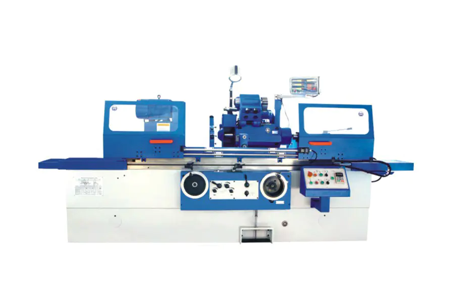
A universal cylindrical grinding machine is a precision machine tool used to grind the outer and inner cylindrical surfaces, tapered surfaces, and shoulders of workpieces. Unlike plain cylindrical grinders, the "universal" designation means both the workhead and the wheelhead can be swiveled to various angles, enabling the machine to handle a much wider range of grinding operations on a single setup. It is widely used in tool rooms, job shops, and precision manufacturing environments where versatility and tight tolerances are essential.
Core Components of a Universal Cylindrical Grinding Machine
Understanding the machine starts with its key structural components, each of which contributes to its versatility and precision:
- Bed: The rigid base, typically made of high-grade cast iron, that supports all other components and absorbs vibration during grinding.
- Workhead (Headstock): Holds and rotates the workpiece. On universal machines, it can be swiveled up to 90° to grind tapered surfaces or perform angular face grinding.
- Tailstock: Supports the other end of the workpiece, adjustable along the table to accommodate different workpiece lengths.
- Table: Reciprocates longitudinally to traverse the workpiece past the grinding wheel. It can also be swiveled slightly (typically ±10°) for grinding shallow tapers.
- Wheelhead: Houses the grinding spindle and wheel. On universal machines, it can be swiveled 360° to allow grinding at any angle, including internal grinding with an internal grinding attachment.
- Internal Grinding Attachment: A motorized spindle that mounts on the wheelhead to enable bore (internal) grinding without re-fixturing the part.
Universal vs. Plain Cylindrical Grinder: Key Differences
The distinction between universal and plain cylindrical grinders is fundamental to choosing the right machine for a given application.
| Feature | Universal Cylindrical Grinder | Plain Cylindrical Grinder |
|---|---|---|
| Workhead Swivel | Yes (up to 90°) | No |
| Wheelhead Swivel | Yes (up to 360°) | No or limited |
| Internal Grinding | Yes (with attachment) | Generally No |
| Taper Grinding | Steep and shallow tapers | Shallow tapers only |
| Face Grinding | Yes | Limited |
| Primary Use | Tool rooms, small-batch, complex parts | High-volume production of simple cylinders |
In short, the universal machine sacrifices some rigidity for flexibility — the swivel joints introduce slightly more setup variables — while the plain grinder is optimized for high-throughput production runs on straightforward geometries.
What Operations Can It Perform?
The "universal" capability means a single machine setup can address multiple grinding tasks:
External Cylindrical Grinding
The most common operation: the workpiece rotates between centers or in a chuck while the grinding wheel removes material from the outer diameter. Surface finish can reach Ra 0.2–0.4 µm and diameter tolerances of ±0.002–0.005 mm are routinely achieved.
Internal Cylindrical Grinding
With the internal grinding attachment swung into position and the workhead set to hold the part in a chuck, bores and holes can be ground to precise diameters and surface finishes — all without moving the part to a dedicated internal grinder.
Taper Grinding
By swiveling the workhead or the table, steep tapers (e.g., Morse tapers, tool shanks) and shallow tapers can both be ground accurately. For example, a Morse Taper No. 4 has an included angle of approximately 2°51′26″ — a geometry easily handled by the workhead swivel.
Face (Shoulder) Grinding
With the wheelhead rotated 90°, the side face of the grinding wheel can be used to grind perpendicular shoulders and faces, ensuring squareness with the cylindrical axis in a single clamping.
Angular and Formed Surface Grinding
A dressed profile wheel combined with a swiveled wheelhead allows the machine to grind complex angular profiles, such as the seats and lands on precision spindles or valve stems.
Workholding Methods Used on Universal Cylindrical Grinders
How the workpiece is held significantly affects accuracy and the operations possible:
- Between Centers: The most accurate method for long shafts. Center holes in each end of the workpiece locate it on hardened dead or live centers. Runout errors can be kept below 0.001 mm.
- Chuck (3-jaw or 4-jaw): Used for short workpieces, or parts without center holes. The 4-jaw independent chuck allows precise offsetting for eccentric grinding.
- Collet: For small-diameter workpieces requiring high concentricity, collets minimize runout compared to jaw chucks.
- Magnetic Chuck or Faceplate: Occasionally used for flat-faced parts or special fixtures.
Typical Specifications and Size Ranges
Universal cylindrical grinders are produced across a wide range of sizes. Typical specification parameters include:
| Parameter | Small/Tool Room | Medium | Large |
|---|---|---|---|
| Max. Grinding Diameter | 150–200 mm | 300–400 mm | 500–800 mm |
| Max. Grinding Length | 500–750 mm | 1000–1500 mm | 2000–4000 mm |
| Grinding Wheel Speed | 1600–2000 rpm | 1200–1600 rpm | 800–1200 rpm |
| Achievable Roundness | 0.001–0.003 mm | 0.002–0.005 mm | 0.003–0.008 mm |
Modern CNC universal cylindrical grinders often add automatic wheel dressing, in-process gauging, and multi-axis simultaneous interpolation, enabling untended operation and consistent tolerances across production runs.
Industries and Applications
Universal cylindrical grinders are found wherever precision shafts, spindles, or bores are required:
- Aerospace: Landing gear shafts, turbine blade root forms, hydraulic actuator rods — components where tolerances of ±0.005 mm or tighter are standard.
- Automotive: Camshafts, crankshafts (journal finishing), transmission shafts, and ABS sensor rings.
- Tool and Die: Grinding punch shanks, die button bores, and precision mold cores to maintain fit and clearance.
- Medical Devices: Orthopedic implant stems, surgical instrument shafts requiring mirror-finish Ra values below 0.1 µm.
- General Engineering: Repair and reconditioning of worn shafts, maintenance of machine tool spindles.
Grinding Wheel Selection for Universal Cylindrical Grinding
The grinding wheel is the cutting tool, and selecting the right specification is critical to achieving the desired finish and material removal rate:
- Abrasive type: Aluminum oxide (A) for steels and ferrous materials; silicon carbide (C) for cast iron, non-ferrous metals, and carbides; CBN (cubic boron nitride) for hardened steels where wheel life and form retention are critical.
- Grain size: Coarser grits (46–60) for roughing passes with high material removal; finer grits (80–120 and above) for finishing passes targeting low Ra values.
- Bond type: Vitrified (V) bonds are most common for cylindrical grinding due to porosity, form-holding, and dressability.
- Hardness grade: Harder grades (H–K) retain the wheel shape longer for plunge grinding; softer grades (F–H) self-sharpen faster for traverse grinding on harder workpieces.
Manual vs. CNC Universal Cylindrical Grinders
Universal cylindrical grinders are available in both conventional (manual) and CNC configurations, each suited to different production scenarios:
Conventional (Manual) Machines
The operator controls table traverse, infeed, and workspeed manually or via handwheels and levers. These machines excel in tool rooms and repair shops where one-off or very small batches of complex parts are produced. Skilled operators can achieve excellent results, but cycle time and repeatability depend heavily on operator experience.
CNC Universal Cylindrical Grinders
CNC control enables programmed grinding cycles, automatic wheel dressing, in-process gauging with automatic compensation, and multi-diameter part programs. A CNC machine can switch between OD grinding, shoulder grinding, and taper grinding within a single program cycle. Part-to-part repeatability of ±0.001 mm is achievable, and batch sizes from 5 to 5,000 pieces become economical with one setup.
Important Operational Considerations
Getting consistent, high-quality results from a universal cylindrical grinder requires attention to several operational factors:
- Machine warm-up: Thermal stability is essential. Most precision shops run the machine for 15–30 minutes before taking final cuts to allow spindle bearings and bed structures to reach thermal equilibrium.
- Wheel dressing: A sharp, correctly dressed wheel is non-negotiable. Dressing frequency depends on the workpiece material and depth of cut — typically after every 10–20 parts in production or whenever surface finish deteriorates.
- Coolant application: Adequate coolant flow (typically 20–40 L/min for medium machines) prevents thermal damage (burn marks) and flushes grinding swarf away from the contact zone.
- Workpiece speed: Workpiece surface speed typically ranges from 15–35 m/min. Harder materials and finer finishes call for lower workpiece speeds.
- Spark-out passes: After reaching final depth, allowing the table to traverse the workpiece 2–4 times without further infeed ("sparking out") eliminates elastic deflection and achieves the final size and finish.
Advantages and Limitations at a Glance
The universal cylindrical grinder is a powerful tool, but like all machine tools, it involves trade-offs:
Advantages
- Can perform OD, ID, taper, shoulder, and angular grinding in one setup, reducing fixturing time.
- Capable of achieving very tight tolerances (roundness <0.001 mm) and fine surface finishes (Ra <0.2 µm).
- Suitable for a wide range of materials including hardened steel, carbide, ceramic, and non-ferrous alloys.
- Highly flexible for prototype, small-batch, and repair work.
Limitations
- More setup time and skill required compared to dedicated production grinders.
- Lower throughput than specialized machines (e.g., centerless grinders) for high-volume simple geometries.
- The swivel joints, if worn, can introduce angular errors that require careful periodic calibration.
- Generally higher initial investment than plain cylindrical grinders of equivalent capacity.


