0086-15068518279 (Chinese)/001-5416026691 (English)



 EN
EN
 中文简体
中文简体Content
- 1 What Is a CNC Cylindrical Grinding Machine
- 2 How the Grinding Process Works Inside the Machine
- 3 Main Structural Components and Why They Matter
- 4 MK and MAK Series Specification Comparison
- 5 Matching a Model to Your Workpiece Size and Batch Volume
- 6 Industries and Parts That Rely on This Equipment
- 7 Grinding Wheel Selection and Cutting Parameters
- 8 Daily Care and Preventive Maintenance
- 9 Common Grinding Defects and Practical Fixes
- 10 Evaluating Cost, Output, and Payback Period
- 11 Frequently Asked Questions
- 11.1 What tolerance can a CNC cylindrical grinding machine achieve.
- 11.2 What is the difference between the MK and MAK model naming.
- 11.3 How often should the grinding wheel be dressed.
- 11.4 Can one machine grind both short and long shafts.
- 11.5 What workpiece weight limits apply to smaller models.
- 11.6 Does a higher wheel peripheral speed always mean faster cycle time.
What Is a CNC Cylindrical Grinding Machine
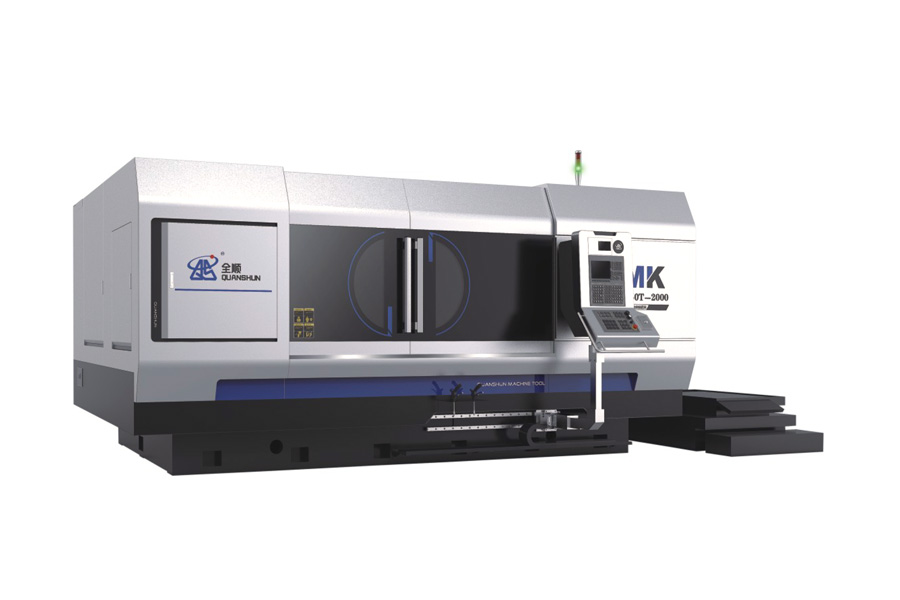
A CNC cylindrical grinding machine is a metal cutting tool that removes a thin layer of material from the outer or inner surface of a round workpiece using a rotating abrasive wheel, while the part itself turns between centers or in a chuck. The letters CNC stand for computer numerical control, meaning the wheelhead, worktable, and infeed axis all move under program instructions rather than manual handwheels. The result is a shaft, roller, pin, or spindle with a diameter tolerance that can reach single digit micron levels and a surface finish far smoother than turning or milling can produce on their own.
In practical terms, this machine is the finishing station that comes after turning or hardening. A shaft is first roughed out on a lathe, then heat treated to raise its hardness, and finally sent to the CNC cylindrical grinding machine to bring the diameter and roundness back within the tight numbers a drawing calls for. Automotive crankshaft journals, hydraulic cylinder rods, machine tool spindles, and bearing seats are grinding work almost every time because turning alone cannot hold the roundness or surface finish these parts need once they are hardened.
How the Grinding Process Works Inside the Machine
Four motions run at the same time once a cycle starts, and understanding them explains why the machine can hold such fine tolerances.
1
Wheel rotation - the grinding wheel spindle turns at a fixed peripheral speed, commonly between 35 and 45 meters per second on the machines covered later in this article, so the abrasive grains cut at a constant rate regardless of workpiece diameter.
2
Workpiece rotation - the part turns slowly between centers or in a headstock chuck, usually a few tens to a few hundred revolutions per minute, so every point on the surface passes the wheel repeatedly.
3
Table traverse - the worktable slides the part back and forth along the wheel face for long shafts, or stays fixed for plunge grinding a short shoulder or groove in one pass.
4
Infeed control - a servo driven ball screw pushes the wheelhead toward the part in steps as small as 0.001mm, which is what lets a CNC machine hold diameters that a manual grinder cannot repeat reliably.
A finishing pass normally follows a rough pass at a heavier infeed rate, then a spark out stage where the wheel makes several passes at zero additional infeed to let the machine spring back settle and to remove any remaining stock. This sequencing is written once into the CNC program and repeated on every part, which is why grinding batches of identical shafts stay far more consistent than parts machined by hand.
Main Structural Components and Why They Matter
Five subsystems decide how accurate and how durable a grinding machine will be over years of production. A buyer comparing machines should look at each one separately rather than judging a machine only by its price tag.
Bed and Base Casting
The bed is a one piece cast iron structure that is aged and stress relieved before final machining, so it does not warp as it absorbs cutting forces and workshop temperature swings over years of use. A heavier, well ribbed casting damps vibration better, and vibration is the single biggest enemy of a fine surface finish.
Wheelhead Spindle
The spindle carries the grinding wheel and can use either rolling bearings or hydrodynamic and hydrostatic oil film bearings. Oil film spindles run cooler under sustained heavy cutting and hold rotational accuracy longer, which is why the higher precision models in the comparison table below quote a boosted wheel speed of 45 meters per second on a dynamic and static pressure spindle option.
Linear Guideways and Ball Screws
Precision linear guides paired with pre loaded ball screws driven by absolute value servo motors remove the backlash that plagued older sliding way designs, giving a minimum programmable infeed step of around 0.001mm on the machines referenced in this article.
Headstock and Tailstock
Center height directly limits the largest diameter a shaft can rotate at without hitting the bed, which is why manufacturers quote center height as a core spec figure rather than an afterthought. The tailstock quill applies steady center pressure so a long slender shaft does not chatter or bend under grinding force.
CNC Control and Conversational Software
A conversational grinding interface lets an operator enter a target diameter, length, and stock removal amount on a fill in the blank screen rather than writing G code by hand, which shortens setup time for shops that run many different small batches rather than one repeat part for months at a time.
MK and MAK Series Specification Comparison
The table below lines up seven common configurations from a working MK and MAK series product line so the numbers can be compared side by side rather than read one data sheet at a time. All figures are manufacturer stated technical parameters for each model.
| Model | Diameter to be Ground | Max Length to be Ground | Center Height | Wheel Size O.D. x W x I.D. | Total Motor Power |
|---|---|---|---|---|---|
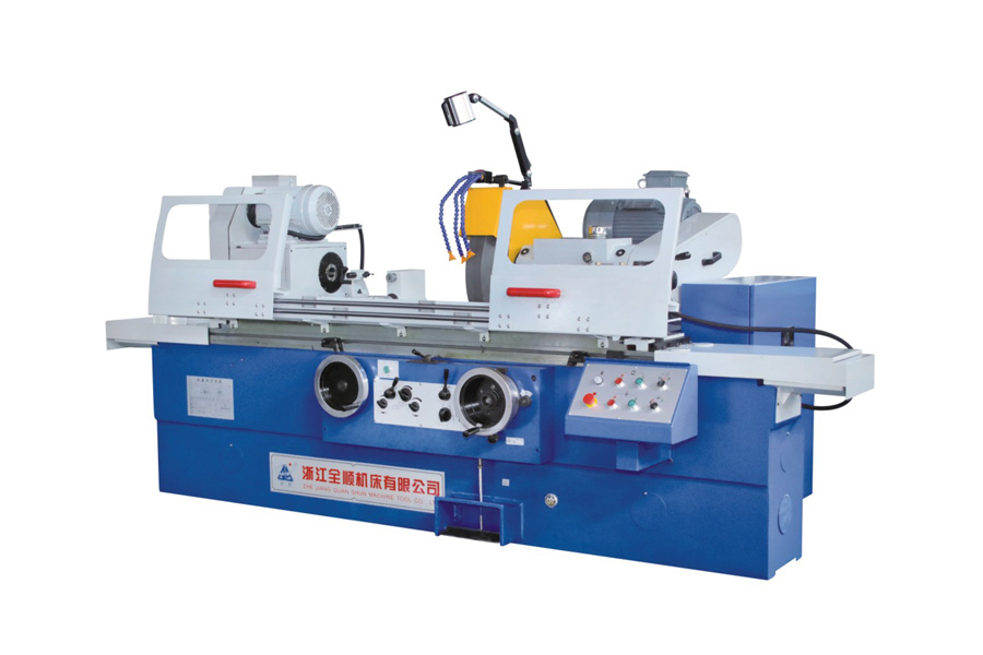
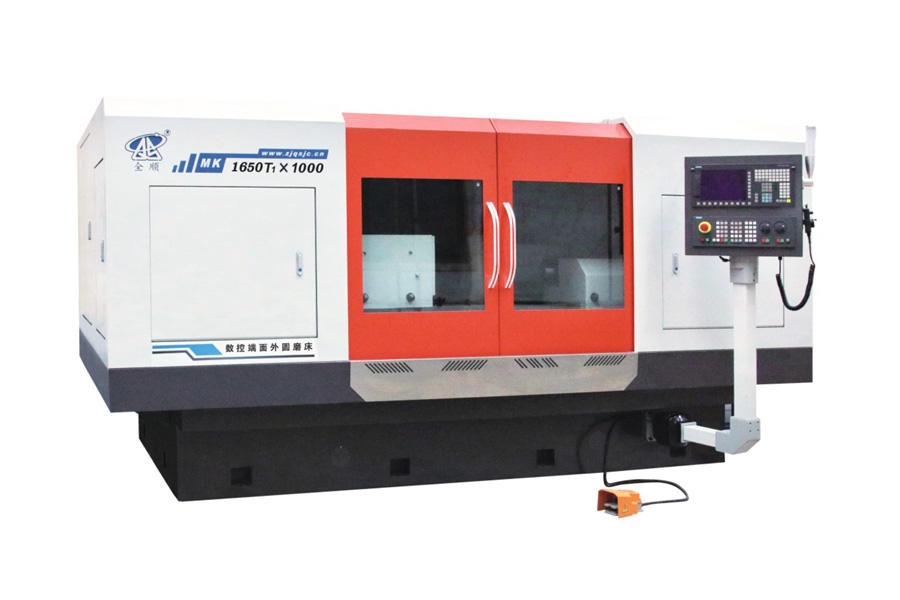
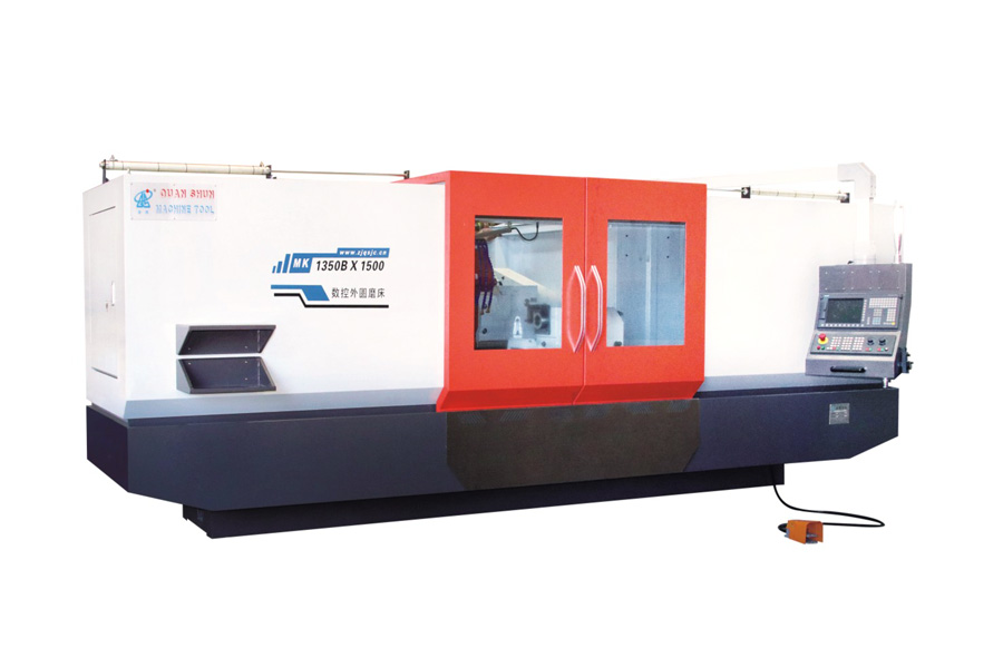
| MK1350B | Max 500mm | 1500 / 2000 / 3000 / 4000mm | 270mm | Phi750x75xPhi305mm | 20.63kW |
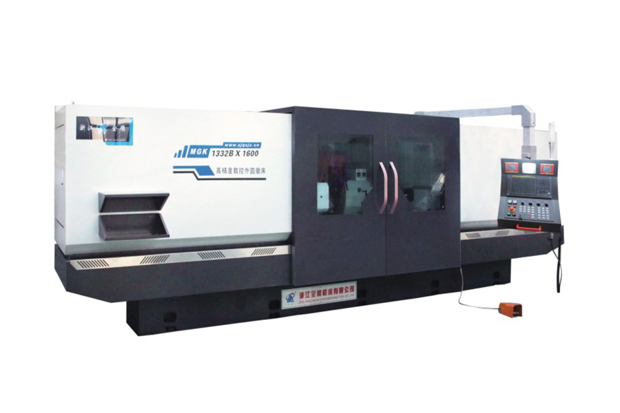
| MK1332B | Phi8 to Phi320mm | 500 / 1000 / 1500 / 2000 / 3000mm | 180mm | Phi600x75xPhi305mm | 21.475 to 33.075kW |
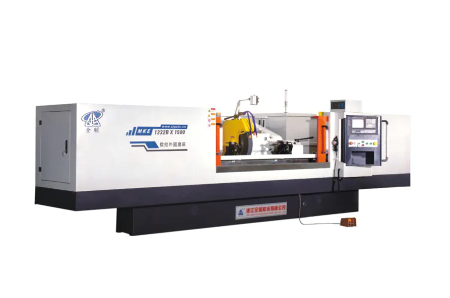
| MKE1332B | Phi8 to Phi320mm | 500 / 1000 / 1500 / 2000 / 3000mm | 180mm | Phi600x75xPhi305mm | 21.475 to 33.075kW |
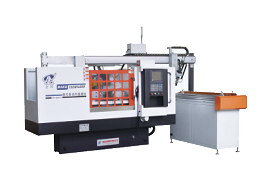
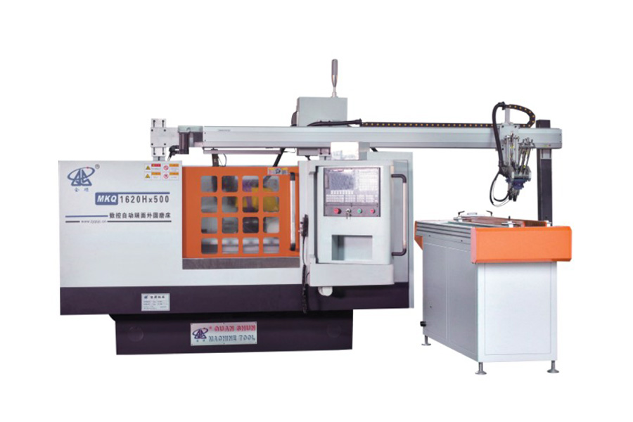
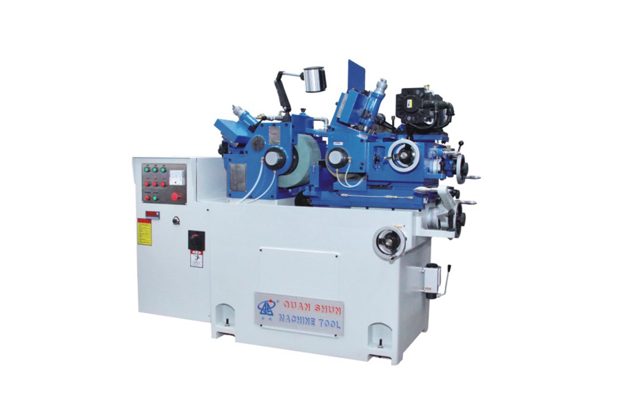
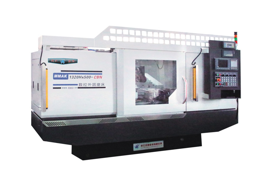
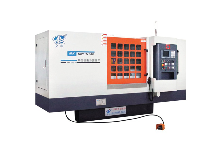
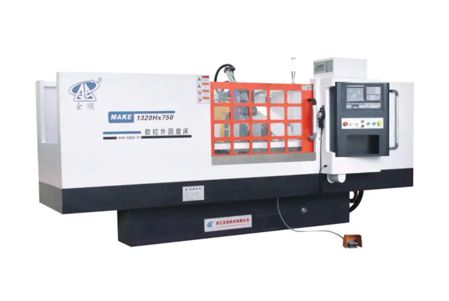
| MAK1320H | Phi8 to Phi200mm | 500 / 750mm | 135mm | Phi500x50xPhi203mm | 10.825kW |
| MAKE1320H | Phi8 to Phi200mm | 500 / 750mm | 135mm | Phi500x50xPhi203mm | 10.825kW |
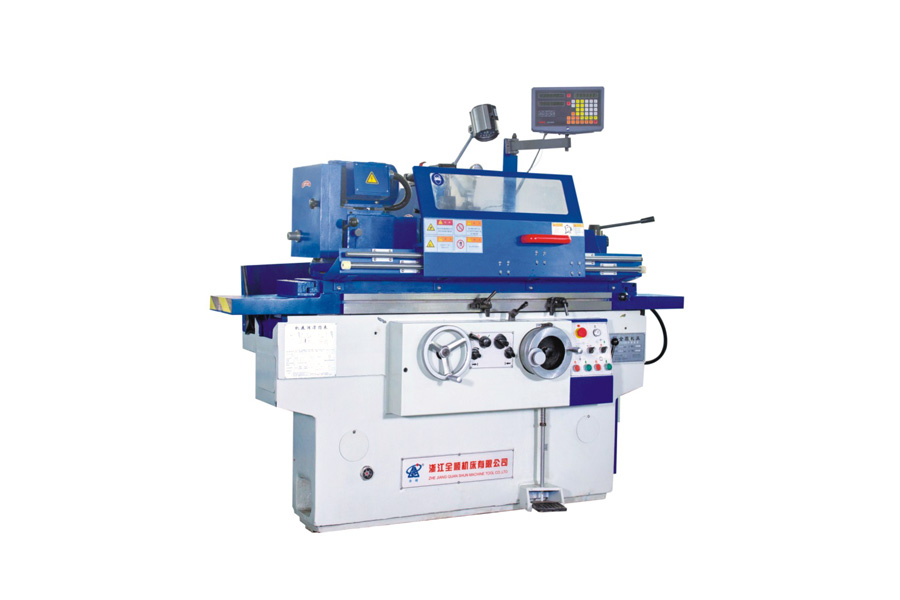
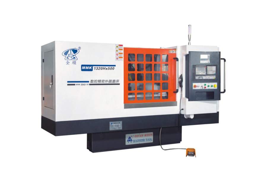
| MK1320H | Phi8 to Phi200mm | 500 / 800mm | 135mm | Phi400x50xPhi203mm | 10.825kW |
| MKE1320H | Phi8 to Phi200mm | 500 / 800mm | 135mm | Phi400x50xPhi203mm | 10.825kW |
Wheel peripheral speed sits at 38 meters per second across the whole range, rising to 45 meters per second when a dynamic and static pressure spindle is fitted, and maximum workpiece weight scales from 50kg on the compact H series up to 1000kg on the MK1350B. Reading this table alongside the part drawing in front of you is the fastest way to shortlist a model, since diameter range and between centers length rule out most options before power or spindle type ever come into the decision.
Matching a Model to Your Workpiece Size and Batch Volume
Three questions narrow a seven model line down to one or two realistic choices before a quote is ever requested.
- What is the largest diameter and longest length in the part family. A shop grinding small pins and short shafts under 200mm diameter and 800mm length fits comfortably on the MK1320H, MKE1320H, MAK1320H, or MAKE1320H, while shafts up to 320mm diameter and 3000mm long call for the MK1332B or MKE1332B, and anything approaching 500mm diameter and 4000mm long needs the MK1350B.
- How heavy is the heaviest single part. Center height and bearing load capacity both track workpiece weight, so a 900kg crankshaft blank has no business being loaded onto a machine rated for 150kg, even if the diameter would technically fit.
- Is stock removal light and repetitive, or heavy and inconsistent. Forged or cast blanks with uneven stock benefit from the extra motor power and larger wheel diameter of the MK1332B and MK1350B, while pre turned bar stock with a small, even grinding allowance runs efficiently on the lower power H series machines.
A simple rule many shop planners use is to size the machine to the largest part expected over the next three to five years rather than only the part in front of them today, since a grinding machine is a long service life asset and upgrading center height or bed length later is rarely practical.
Industries and Parts That Rely on This Equipment
Cylindrical grinding shows up wherever a round part must mate with another round part along a tight tolerance fit, so the application list spans far beyond one single industry.
| Industry | Typical Parts Ground | Typical Tolerance Target |
|---|---|---|
| Automotive and engine parts | Crankshaft and camshaft journals, gearbox shafts, piston pins | 0.005mm to 0.01mm |
| Hydraulic and pneumatic components | Cylinder rods, plungers, valve spools | 0.005mm to 0.02mm |
| Bearing manufacturing | Inner and outer bearing races, roller pins | 0.002mm to 0.008mm |
| Machine tool building | Spindles, precision leadscrews, guide shafts | 0.003mm to 0.01mm |
| Textile and printing machinery | Rollers, drive shafts, printing cylinders | 0.01mm to 0.02mm |
Long roll and cylinder work, such as printing rollers or textile drive shafts, is exactly the category that pushes shops toward the longer bed options in the MK1332B and MK1350B range, since bed length between centers rather than diameter is usually the limiting spec for these parts.
Grinding Wheel Selection and Cutting Parameters
Wheel choice affects surface finish and cycle time as much as the machine itself does, so pairing the right abrasive with the right infeed rate matters just as much as picking the right model.
Abrasive Type by Material
- Aluminum oxide wheels suit carbon steel and alloy steel shafts, covering the large majority of automotive and general engineering grinding work.
- Cubic boron nitride wheels suit hardened steel above 55 HRC and hold their shape far longer than conventional abrasive on repeat production runs.
- Silicon carbide wheels suit cast iron, bronze, and other non ferrous or brittle materials where aluminum oxide would glaze over quickly.
Typical Cutting Parameters
A rough grinding pass commonly removes 0.02mm to 0.05mm of radial stock per pass at a table speed suited to the wheel width, followed by a finish pass at 0.005mm to 0.01mm per pass, and a spark out stage of two to four passes with zero additional infeed. Coolant flow, usually a water soluble grinding fluid, needs to reach the wheel and part contact zone continuously, since heat buildup in this small contact area is what causes grinding burn and residual stress in the finished part.
Daily Care and Preventive Maintenance
Consistent daily habits keep a grinding machine holding its rated accuracy for many years rather than drifting out of tolerance within months.
| Interval | Task |
|---|---|
| Every shift | Check coolant level and flow, wipe down guideways, inspect wheel for chips or glazing |
| Weekly | Dress the grinding wheel, clean coolant filter or magnetic separator, check way lubrication oil level |
| Monthly | Check spindle running temperature, inspect ball screw and linear guide for play, verify center alignment |
| Quarterly | Full coolant tank cleaning, check tailstock quill pressure, run a geometric accuracy check with a test bar |
Coolant condition deserves special attention, since dirty or depleted coolant is the most common root cause of both poor surface finish and premature wheel wear, yet it is also the cheapest single item on this list to fix.
Common Grinding Defects and Practical Fixes
| Symptom | Likely Cause | Suggested Fix |
|---|---|---|
| Blue or brown discoloration on the surface | Grinding burn from excess heat | Reduce infeed rate, increase coolant flow, dress the wheel |
| Wavy chatter marks along the length | Spindle imbalance or loose tailstock support | Rebalance the wheel, check center pressure, inspect bearing wear |
| Tapered diameter along the part length | Misaligned centers or worn tailstock quill | Recheck center alignment with a test indicator, service the tailstock |
| Rough or dull looking surface finish | Glazed or loaded wheel face | Dress the wheel more frequently, confirm the abrasive grade matches the material |
Evaluating Cost, Output, and Payback Period
Purchase price is only one part of the ownership cost picture. A realistic evaluation weighs at least four factors together.
- Cycle time per part, which depends on wheel speed, infeed step size, and how much of the process is automated versus manually loaded.
- Power consumption, where total motor power in the specification table gives a starting point for estimating electricity cost per shift.
- Wheel and coolant consumables, which scale with wheel diameter and how aggressively rough passes remove stock.
- Scrap and rework rate, which a repeatable CNC infeed system tends to lower compared to manual grinding, directly improving effective throughput.
Shops that run a narrow part mix at high volume usually recover the machine cost fastest through cycle time gains, while shops running many different small batches recover cost mainly through reduced setup time from conversational programming and fewer scrapped parts during first article setup.
Frequently Asked Questions
What tolerance can a CNC cylindrical grinding machine achieve.
Most industrial CNC cylindrical grinders hold diameter tolerances between 0.005mm and 0.02mm in normal production, and machines fitted with dynamic and static pressure spindles combined with in process gauging can reach single digit micron repeatability on critical bearing or spindle work.
What is the difference between the MK and MAK model naming.
Within this product family, the MK prefix denotes the standard CNC cylindrical grinding configuration while the MAK prefix denotes a compact configuration built for shorter, smaller diameter shafts, and an added E in the model code such as MKE or MAKE typically indicates an enhanced control or drive option on that same base machine.
How often should the grinding wheel be dressed.
Dressing frequency depends on material hardness and stock removal rate, but a practical starting point for most steel work is to dress before every finishing pass on critical diameters and at minimum once per shift for general production runs, adjusting sooner if surface finish or cycle sound changes noticeably.
Can one machine grind both short and long shafts.
Yes, provided the between centers length falls within the machine bed rating, which is why models such as the MK1332B are offered in five different bed lengths from 500mm up to 3000mm on the same base machine, letting a shop match bed length to its typical part range without paying for unused travel.
What workpiece weight limits apply to smaller models.
The compact 1320H series covered in the comparison table is rated for a maximum workpiece weight of 50kg, while the mid range MK1332B and MKE1332B step up to 150kg, and the larger MK1350B is rated for parts up to 1000kg, so matching part weight to the correct model protects both center accuracy and bearing life.
Does a higher wheel peripheral speed always mean faster cycle time.
Not directly. A higher peripheral speed such as the 45 meter per second option available with a dynamic and static pressure spindle mainly improves surface finish consistency and wheel life at a given stock removal rate, while actual cycle time also depends on infeed step, table traverse speed, and how much stock the rough pass removes.